
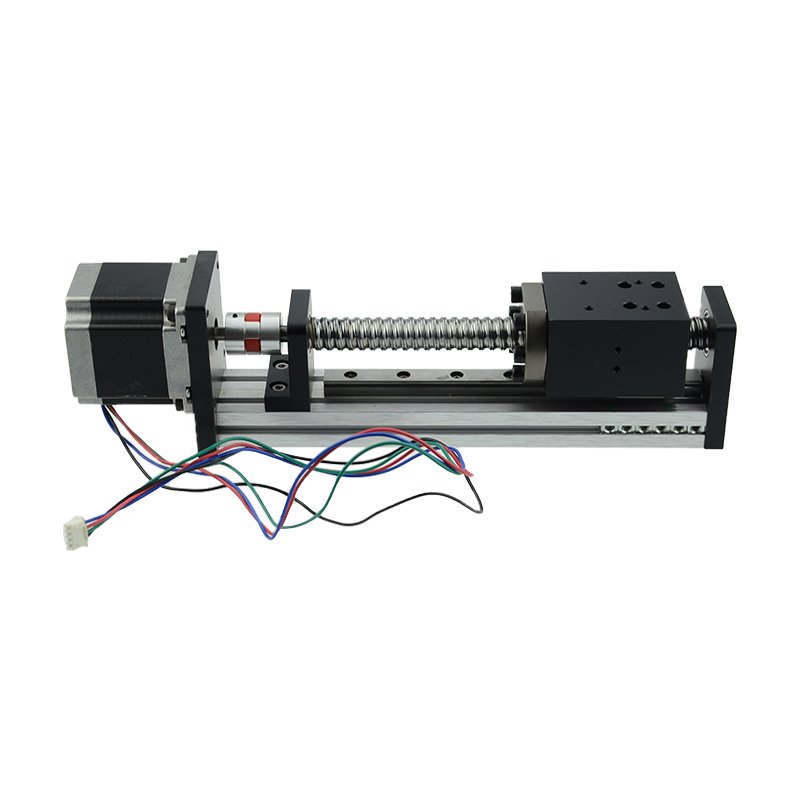
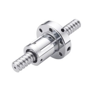
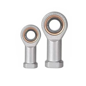
A ball screw sliding module moves a guided carriage along a linear axis. Start with the usable stroke, the payload and its position on the carriage, and the space available at each end of the slide.
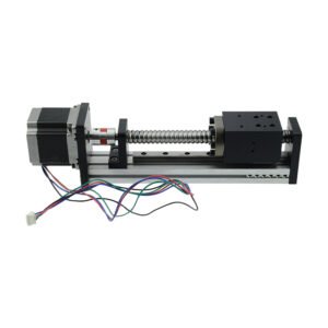
The example shows an exposed screw between parallel guide rods, a carriage and an end-mounted motor. Leave room for carriage travel, the motor and coupling, and access to the screw and guides for service.
Stroke, Mounting and Payload
- Stroke: Mark the usable travel, end clearances and home or limit positions.
- Base and Carriage: Provide mounting hole patterns, locating surfaces, datums and the payload’s offset from the carriage.
- Operating Loads: Specify mounting orientation, axial and side loads, speed, acceleration and duty cycle.
Ball Screw, Guides and Drive Interface
Specify the screw diameter, lead, nut arrangement and end supports. For C5 or C7, state the applicable standard, effective thread length and the lead-error measurement to be verified. Use separate acceptance criteria for the assembled slide.
Dimension the guide spacing and the motor flange, shaft and coupling interface. Identify any servo or stepper motor, sensors, supports or coupling to include in the quote. Specify guarding and lubrication access for the open layout. For a housed layout, see the embedded screw rod module.
Materials and Surface Treatment
Review aluminum alloy for the module structure and alloy steel for the screw. Specify the grade and condition for each part. Mark the surfaces requiring anodizing, hardening, grinding or a protective finish, and identify any mating or locating surfaces with separate requirements. Explore our CNC machining processes.
Positioning and Inspection References
- Axis Positioning: Review ±0.01–0.03 mm positioning accuracy and ±0.005–0.01 mm repeatability as separate requirements. Define travel points, load, approach directions and reporting method.
- Backlash: If the preloaded slide requires ≤0.01 mm, specify the preload, reversal procedure and measurement load.
- Straightness: For ≤0.03 mm / 1000 mm, identify whether the requirement applies to a part or the travel path, and specify the measured length, datum and support condition.
- Part Dimensions: Use ±0.02–0.05 mm as a drawing reference for identified dimensions.
If the project calls for a 90% drive efficiency target, agree the input and output measurements and the load, speed, direction and lubrication for the test.
Request a Ball Screw Slide Quote
Send the part and assembly drawings, stroke, screw and guide configuration, operating conditions, quantity and required inspection records.
Discuss your ball screw slide project or email eleven@grancen.com.
Reviews
There are no reviews yet.