
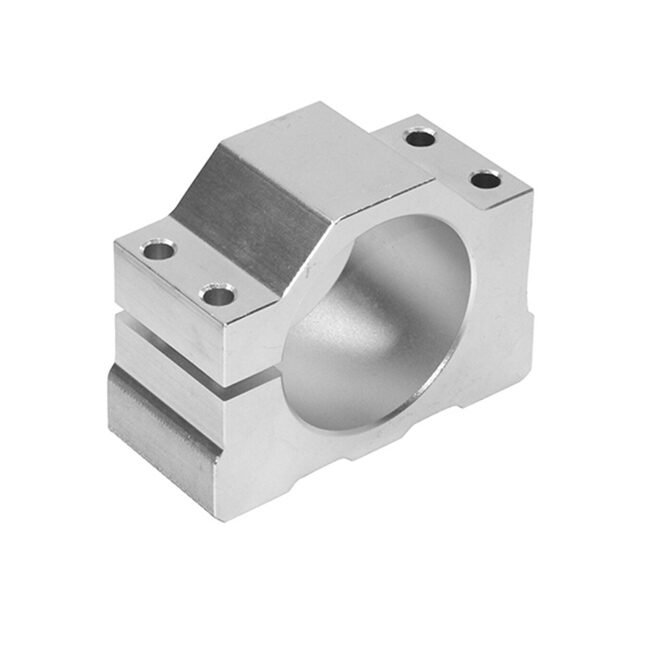
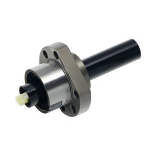
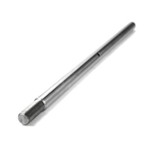
A spindle motor clamp holds a cylindrical motor housing against a machine’s mounting surface. Use the motor maker’s installation drawing to define the clamping zone, housing diameter, and allowable clearance around the motor.
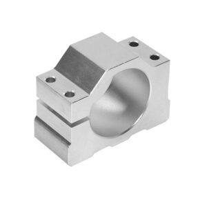
Spindle Housing and Clamping Zone
Provide the exact spindle model, housing outside diameter and tolerance, allowable clamping length, and axial location of the clamp. Mark the clamping zone specified by the spindle maker and show access for the clamp screw.
Machine Interface and Clearances
- Mounting: Send the machine or slide drawing with the mounting face, hole pattern, fastener clearance, and required spindle centerline location.
- Clearance: Show the space needed for connectors, cooling lines, and tool changes. State the fastener supply and any special assembly requirements.
Material and Surface Finish
6061 and 7075 machined aluminum, or cast aluminum with CNC finishing, can be reviewed to the drawing. Specify the alloy and natural, black, or custom anodizing where applicable, or define a coating for a cast part. Mark the clamp bore and mounting face where finish thickness is controlled. Explore our CNC machining processes.
Bore Fit, Slot and Inspection
Drawing references include an H7 bore or a separately specified bilateral bore tolerance of ±0.01–0.02 mm, a clamp slot tolerance of ±0.02–0.05 mm, and general dimensions of ±0.05 mm where specified. State whether the bore is to be measured free or assembled under defined conditions. Use the mounting face and other drawing datums to locate the spindle axis for inspection.
Request a Spindle Motor Clamp Quote
Share the spindle model and mounting drawing, machine hole pattern, clamping zone, bore fit, material, finish, and quantity.
Discuss your spindle motor clamp project or email eleven@grancen.com.
Reviews
There are no reviews yet.