
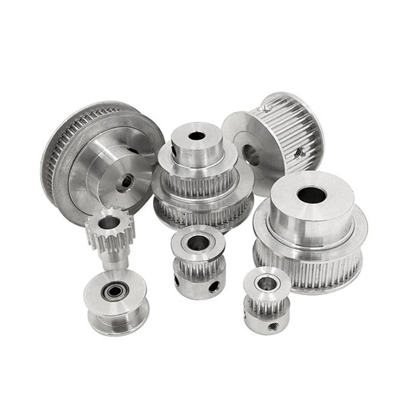
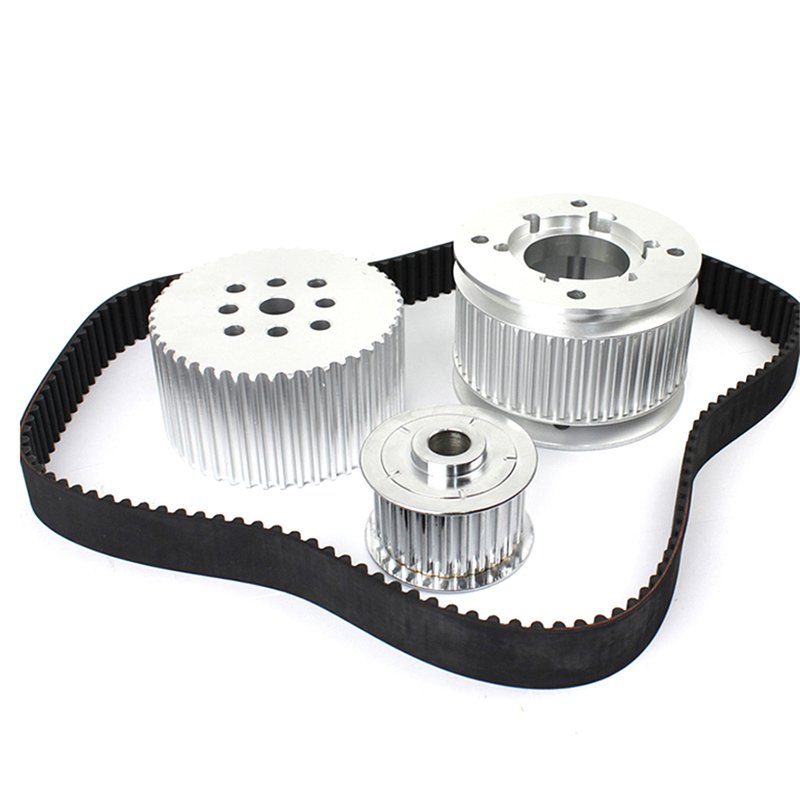
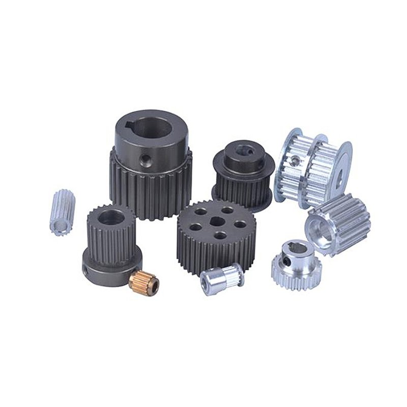
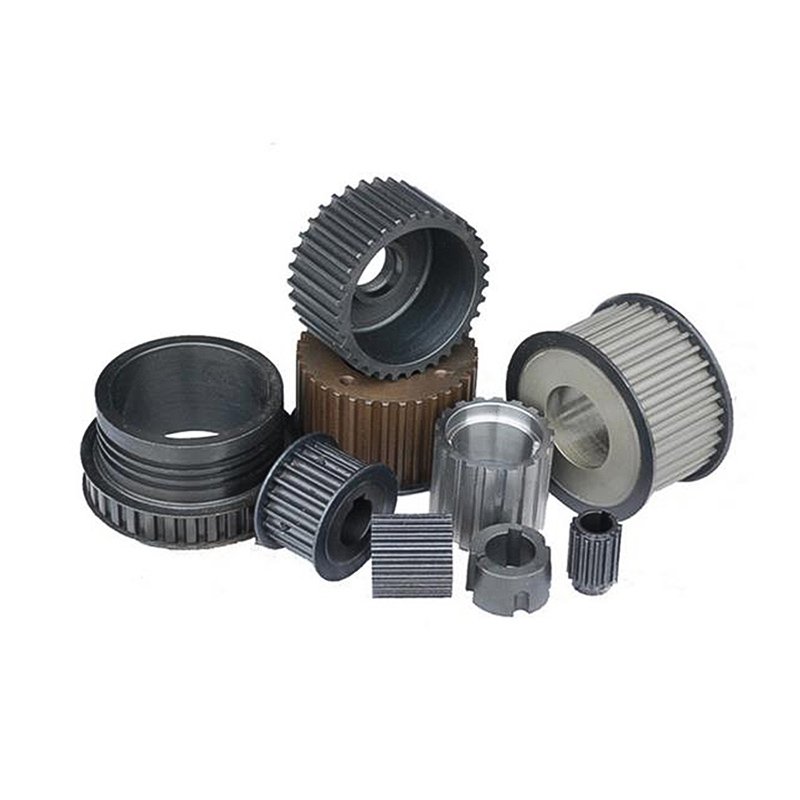
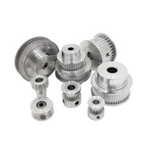
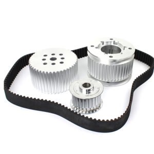
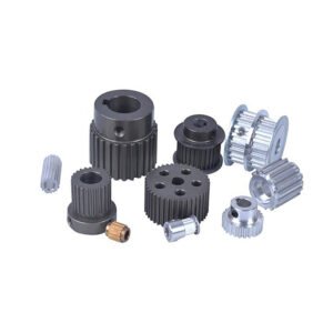
Timing pulleys mesh with a toothed belt to transfer motion between shafts in automation and machinery. Start with the belt designation and pulley drawing so we can review tooth engagement, shaft fit, and assembly clearance together.
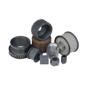
Belt Profile, Pitch and Width
- Belt match: Supply the exact belt manufacturer and series, tooth profile, and pitch. HTD, GT2, T and AT are examples for drawing review.
- Pulley geometry: Specify tooth count, belt width, usable face width, and flange locations. Dimension the outside diameter separately from the pitch diameter.
Bore, Hub and Shaft Connection
Send the shaft diameter and fit, hub length, and available axial space. Identify whether the design uses a pilot bore for later machining, a finished bore, a keyway or set screw, or a specified taper-lock bushing. Include the bushing designation and any retaining hardware requirements.
Material and Finish Options
Drawing options include 6061 or 7075 aluminum, carbon steel, and alloy steel. Specify the grade and finish, such as anodizing for aluminum or black oxide or plating for steel. Mark tooth and bore surfaces with fit or coating requirements. Explore our CNC machining processes.
Dimensions and Inspection
- Bore and outside diameter: Drawing references include an H7 bore or a separately specified bilateral bore tolerance of ±0.01–0.02 mm, an OD tolerance of ±0.02–0.05 mm, and general dimensions of ±0.05 mm where specified.
- Geometry: Drawing references include concentricity ≤0.02 mm and runout ≤0.02 mm. Identify the inspected features, datum axis, gauge setup, and whether runout is radial or axial.
- Surface roughness: For drawing requests in the Ra 0.8–1.6 μm range, give one maximum value for each controlled surface. Include speed, torque and any balance requirement in the inquiry.
Request a Timing Pulley Quote
Share the pulley drawing, belt designation, tooth count, shaft connection, material, finish, quantity, and inspection requirements.
Discuss your timing pulley project or email eleven@grancen.com.
Reviews
There are no reviews yet.