
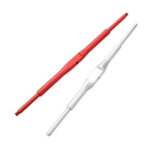
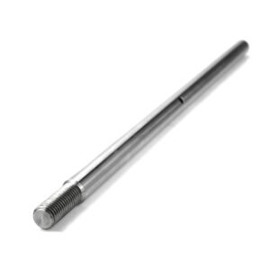
A guide slider supports and guides linear travel along a matching rail. For a replacement block or a new machine axis, start with the rail profile, mounting pattern, block envelope and load on the carriage.
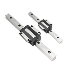
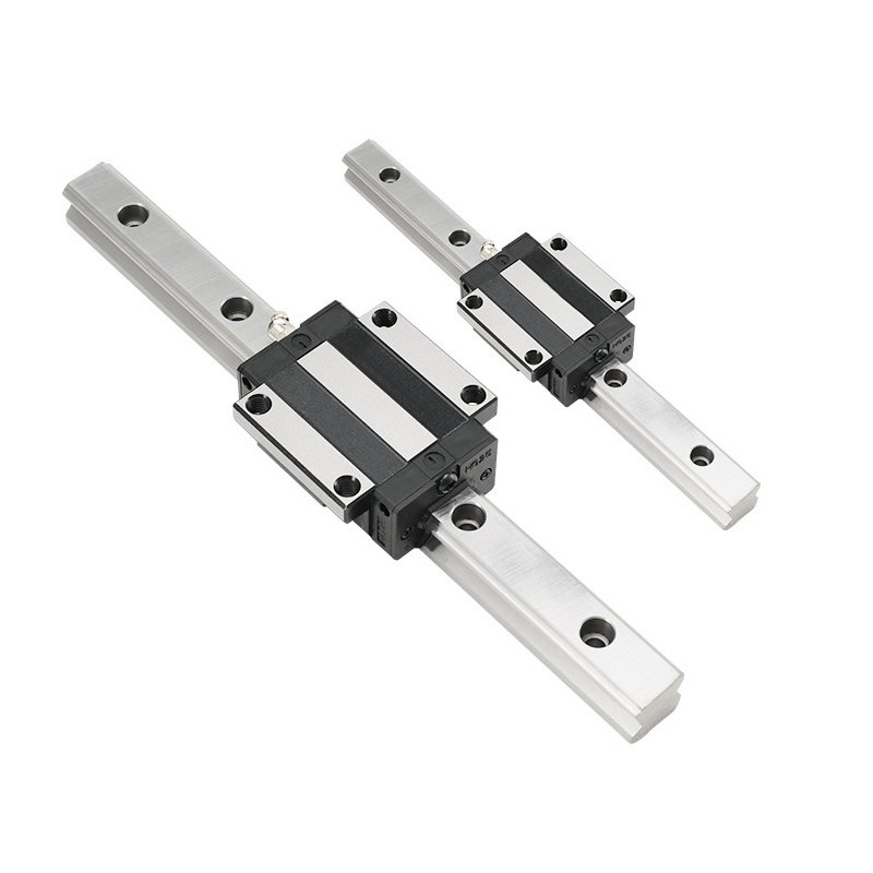
The examples show bearing blocks fitted to rails with spaced mounting holes. Include the rail and block drawings or the existing part numbers so both interfaces can be reviewed together.
Rail and Block Interfaces
- Rail: Specify the profile, width, length, mounting hole pitch and reference side.
- Block: Provide the mounting hole pattern, assembled height, width and allowable envelope. Confirm whether the quote covers a block, a matched block and rail, or a multi-rail set.
- Installation: Give the mounting direction, number of blocks and rails, block spacing and base datums. Include required height matching across parallel rails.
Load, Clearance and Preload
Specify load direction, offset and moment loads, travel speed, duty cycle and signs of shock or vibration in the application. Review the clearance or preload class for the matched set. If the drawing uses light, medium or heavy preload, include the applicable class or measured requirement.
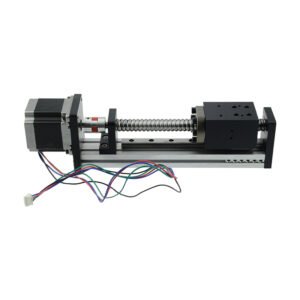
Specify standard recirculating balls or a caged-ball design if required, together with the seals, wipers and lubricant access. For a screw-driven assembly, see the ball screw sliding module.
Material, Raceway and Finish
Review GCr15 bearing steel or the specified stainless grade for each component. Mark any heat treatment, ground raceways or protective finish and list the surfaces to inspect after finishing. Include exposure to moisture, dust or coolant and the required maintenance access. Explore our CNC machining processes.
Rail Geometry and Axis Acceptance
- Parallelism: For a ≤0.02 mm reference, identify the surfaces and datum. For running parallelism, define the mounting reference, travel length and measurement direction.
- Positioning and Repeatability: Review ±0.01–0.02 mm positioning accuracy and ±0.005–0.01 mm repeatability on the assembled axis. Specify travel points, load and test direction.
- Raceway Finish and Dimensions: Define a single maximum for each surface using Ra ≤ 0.4–0.8 μm as a reference. Use ±0.02–0.05 mm as a reference for identified part dimensions.
Request a Guide Slider Quote
Send the rail and block drawings, current model if replacing a block, load and travel requirements, clearance or preload, material, quantity and required inspection records.
Discuss your guide slider project or email eleven@grancen.com.
Reviews
There are no reviews yet.