
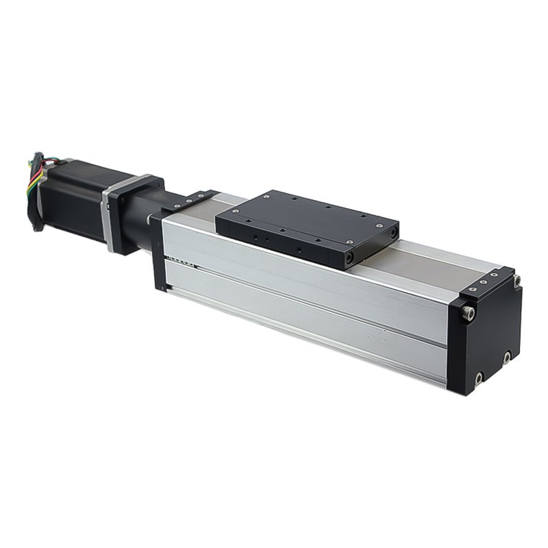
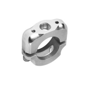
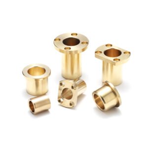
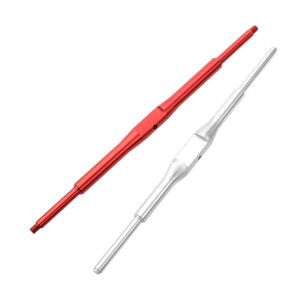
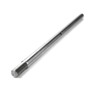
An embedded screw rod module combines a screw drive and guided carriage in one housing. For a compact positioning axis, start with the working stroke, installed envelope and the interface between the carriage and the moving load.
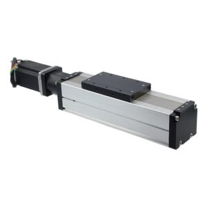
The example shows a rectangular carriage and an end-mounted motor. Dimension the carriage mounting pattern, motor clearance and space needed for cable routing on the assembly drawing.
Stroke and Mounting Interfaces
- Travel: Provide the working stroke, required end clearances and home or limit switch locations.
- Base and Carriage: Dimension the mounting pattern, locating features and datums. Give the load’s offset from the carriage and the required mounting orientation.
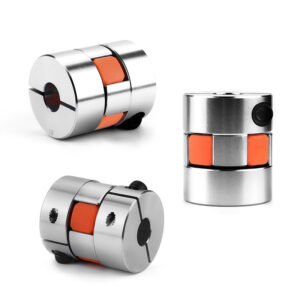
- Motor End: Specify the flange, shaft and coupling interface. Allow room for the motor, connectors and service access.
Drive Selection and Supply Scope
Identify a sliding-nut lead screw or recirculating ball screw for review. Provide the lead, travel speed, load, acceleration and duty cycle. Specify whether the quote should include only machined components, a mechanical module, or the motor, sensors and associated hardware.
State the exposure to dust, chips or fluids and specify any cover, sealing or lubrication requirements. For a vertical axis, define how to hold the load when power is off.
Housing, Screw and Surface Finish
Review the aluminum alloy housing and alloy steel screw by component and grade. Mark anodized surfaces and any areas requiring hardening or coating. Identify the mounting and guide surfaces to inspect after finishing. Explore our CNC machining processes.
Positioning and Inspection References
- Positioning: Review ±0.01–0.03 mm for positioning accuracy and ±0.005–0.01 mm for repeatability separately. Define the assembled state, load, measurement points, approach directions and number of cycles.
- Backlash: For a ≤0.01 mm requirement, specify the measurement point, loading and reversal procedure.
- Straightness: For ≤0.03 mm / 1000 mm, identify the feature or travel path, datum, measured length and mounting condition.
- Guide Finish and Dimensions: Use Ra ≤ 0.8 μm and ±0.02–0.05 mm as references for the named guide surfaces and dimensioned features respectively.
Request an Embedded Screw Module Quote
Send the drawings and stroke, mounting and motor interfaces, load, speed, drive type, material, quantity and required inspection records.
Discuss your screw module project or email eleven@grancen.com.
Reviews
There are no reviews yet.