

Solar Panel Rails
Custom aluminum rail profiles and machined mounting interfaces
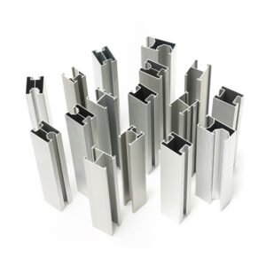
Solar panel rails provide the profile interfaces specified for module clamps, brackets and rail connections. The image shows upright rail sections with different hollow and slotted cross-sections. Select the required section from a drawing so its clamp engagement, fastening features and mating connections can be reviewed together.
Material options include aluminum alloy 6063-T5 / 6061-T6. Specify the alloy and temper, section dimensions and finish. Profile feasibility, extrusion tooling, cut length and any secondary machining are confirmed for the individual project.
Profile and Length Requirements
- Cross-Section: Provide the profile drawing, wall sections, slots and critical mating dimensions.
- Design Brief: Define standard, heavy-duty or custom profile requirements through the section drawing and project acceptance criteria.
- Cut Length: State the required finished length. Examples such as 1m–6m require review of the profile, cutting and handling requirements.
- Machined Features: Dimension holes, slots and end details, including their positions along the rail. Feature access and machining travel are reviewed separately from the overall cut length.
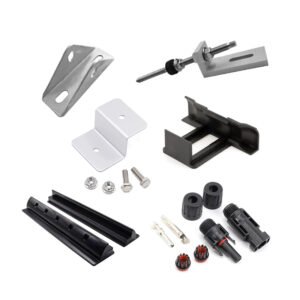
- Connections and Packing: Specify clamps, brackets, splice interfaces and the packaging requirements for the agreed rail lengths.
The mounting-system designer defines spans, support locations, wind and snow load cases, applicable project standards and assembly-verification criteria. Include those requirements with the rail specification.
Tolerance & Dimensions
Define the critical section and machined-feature limits on the drawing. Review the figures below against the alloy, profile, length and finish. For straightness, agree the measurement length, reference datum, support conditions and acceptance method.
- Length Tolerance: ±0.5–1.0 mm, depending on rail length
- Profile Dimension Tolerance: ±0.05–0.10 mm
- Straightness: ≤1 mm per meter
- Hole Position Tolerance: ±0.05 mm
- Surface Roughness: Ra ≤ 1.6–3.2 μm
- General Dimensional Tolerance: ±0.05–0.10 mm
Extrusion and Secondary Machining
The manufacturing route is selected from the profile drawing, material condition and quantity. It may include:
- Aluminum extrusion using the agreed profile tooling
- Straightening and profile calibration to the specified requirements
- Cutting to the agreed finished lengths
- CNC drilling, slotting and other specified mounting features
- Deburring and end finishing
- Clear or black anodizing, or another specified coating and color
- Inspection of agreed section dimensions, length, straightness, hole positions and appearance
Any structural or load verification requires a defined rail and connection assembly, load case and acceptance plan.
PV Rail Applications
Profile designs can be reviewed for roof-mounted and ground-mounted PV structures in residential, commercial, industrial or solar-farm projects. Confirm the actual clamp, bracket and support interfaces for the intended assembly.
Send Your Rail Specification
Provide the cross-section and machining drawings, alloy and temper, cut lengths, finish and quantities. Include mating profiles, critical dimensions, inspection criteria and handling or packing requirements.
Explore our CNC machining processes or submit your solar rail requirements for review. You can also email eleven@grancen.com.
Reviews
There are no reviews yet.