
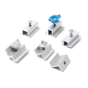
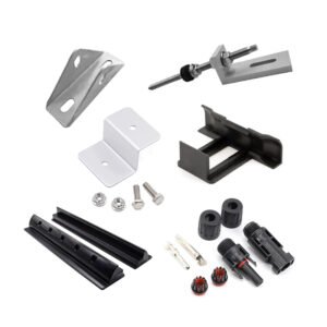
Solar Panel Mounting Bracket
Custom brackets and support components for PV mounting assemblies
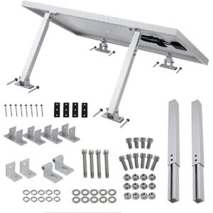
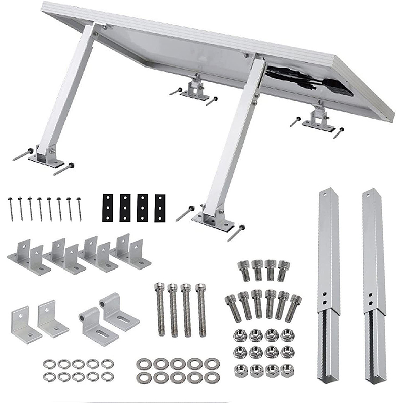
A solar panel mounting bracket connects specified parts of a PV support assembly. The image shows an assembled support frame above a selection of legs, brackets and fasteners. Use the assembly drawing to define the required components, their positions and the interfaces between them.
Material options include aluminum alloy (6061/6063) and stainless steel (SUS304/SUS316). Specify the grade, material condition, section thickness and finish. The selected material and bracket geometry guide the extrusion, cutting, machining, forming or joining route.
Bracket Geometry and Connections
- Fixed or Adjustable Design: Define the support geometry, mating positions and any adjustment features on the drawing.
- Mounting Faces: Provide the hole pattern, slots, contact areas and adjoining component dimensions.
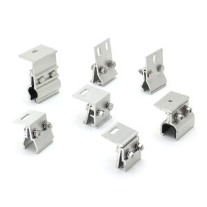
- Rail and Clamp Interfaces: Identify the actual profiles, fasteners and required clearances.
- Assembly Layout: Show the bracket arrangement and the supporting structure specified for the project.
- Finish Requirements: Define the installation environment, appearance and surface treatment for each material.
The project designer defines wind, snow and other load cases for the complete mounting assembly. Include the applicable load-related acceptance criteria and connection requirements with the part drawings for manufacturing review.
Tolerance & Dimensions
Mark critical dimensions, datums and inspection points. Confirm the figures below for the selected material, bracket size, forming sequence and finish, and agree the required feature limits during project review.
- Thickness Tolerance: ±0.05–0.10 mm
- Hole Position Tolerance: ±0.05 mm
- Angle Tolerance: ±0.5°
- Flatness: ≤0.3–0.5 mm
- Surface Roughness: Ra ≤ 1.6–3.2 μm
- General Dimensional Tolerance: ±0.05–0.10 mm
Manufacturing and Finish
The production route is selected from the drawing and quantity. It may include:
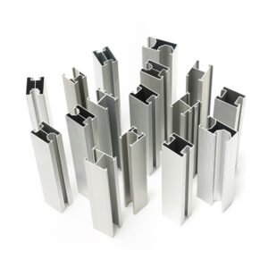
- Aluminum extrusion for suitable structural-profile designs
- CNC milling, drilling, slotting and thread tapping
- Laser cutting and bending of sheet metal brackets
- Welding where a multi-part assembly is specified
- Deburring and edge finishing
- Anodizing for suitable aluminum parts, or passivation for suitable stainless steel parts
- Specified coating, identification or logo marking
- Inspection of agreed dimensions, mounting features, finish and fit
Any load verification needs a project-defined assembly, load case, fixture and acceptance plan.
Mounting-Project Applications
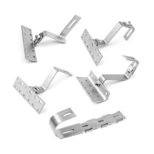
Bracket designs can be reviewed for roof-mounted or ground-mounted PV projects. For metal, tile or flat-roof applications, provide the specified support and connection layout. Fit and configuration are confirmed against those project interfaces.
Send Your Bracket Drawings
Provide the bracket and assembly drawings, material grade, finish and quantity. Include the mating rail or clamp profiles, fastening requirements, critical dimensions and any prototype or inspection criteria.
Explore our CNC machining processes or sheet metal fabrication processes, then submit your mounting bracket requirements for review. You can also email eleven@grancen.com.
Reviews
There are no reviews yet.