
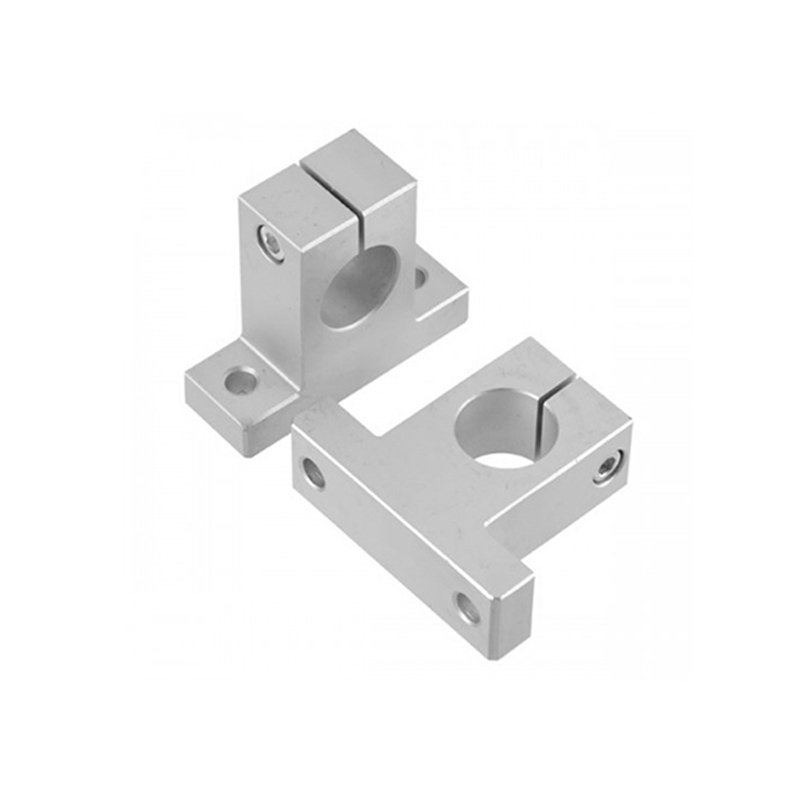
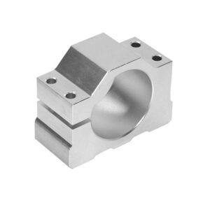
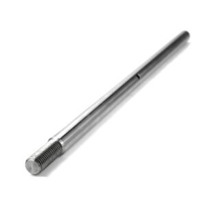
A linear shaft support holds a round guide shaft at a fixed position on a mounting base. Specify the shaft diameter, center height, and base hole pattern so the support can be reviewed with the rest of the linear-motion assembly.
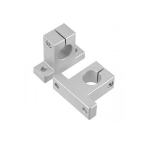
Shaft Fit and Clamp Access
Provide the shaft outside diameter and tolerance, the support bore fit, and the clamp screw size and access. The support fixes the shaft to the base. A separate linear bushing or carriage moves along the shaft in a typical assembly.
Mounting Base and Center Height
- Base: Specify the seating face, slot or hole locations, clearance, and any alignment features. Give the thread size, pitch, and depth for tapped holes.
- Center height: Dimension the shaft axis from the base seating face. For paired supports, specify whether heights must match and how the two centers are checked after mounting.
- Assembly: Provide support spacing, unsupported span, and load direction for system-level review.
Aluminum Grade and Finish
6061 or 6063 aluminum can be specified on the drawing. Define natural, black, or custom anodizing and identify the bore or mounting face if fit or coating thickness is controlled there. Explore our CNC machining processes.
Dimensions and Inspection
Drawing references include an H7 bore or a separately specified bilateral tolerance of ±0.01–0.02 mm, center height of ±0.02–0.05 mm about the nominal dimension, and general dimensions of ±0.05 mm where specified. Supply the mounting datum and specify the clamp condition when acceptance depends on the installed assembly.
Request a Linear Shaft Support Quote
Send the support and shaft drawings, bore fit, center height, base hole pattern, material, finish, and quantity. Include any matching or inspection requirement for paired supports.
Discuss your linear shaft support project or email eleven@grancen.com.
Reviews
There are no reviews yet.