Carbon Fiber Products & Manufacturing Processes

Carbon-fiber tubes, profiles, molded components and CNC-finished plates. Explore the product forms and manufacturing processes.

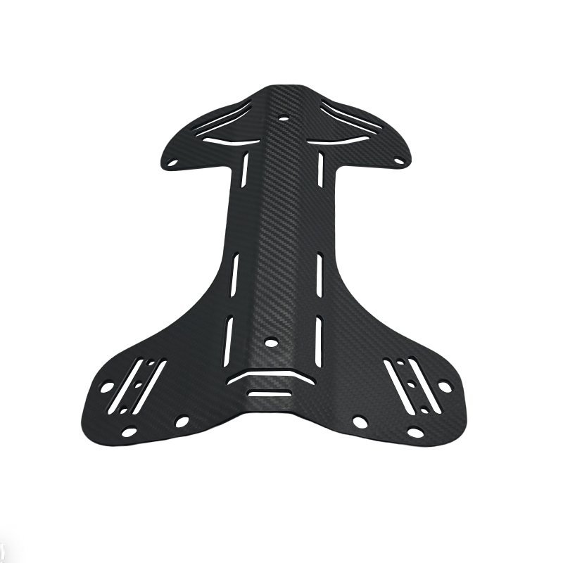
Carbon fiber frame plate showing woven surface, routed openings and mounting holes

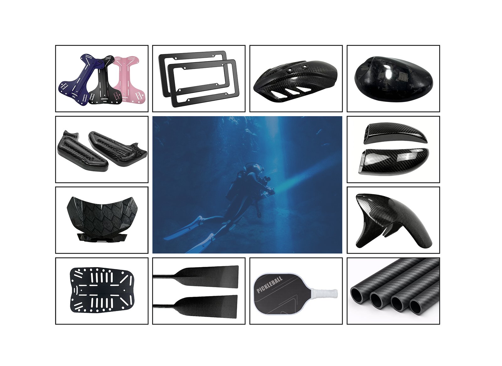
Carbon Fiber Product Examples

Examples of tubular, flat and molded composite components.

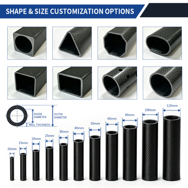
Two Tube Designs

Carbon fiber tubes shown in different diameters

Custom Carbon Fiber Tubes

Straight composite tubes for frames and supports. Roll wrapping is one route for suitable tube designs, followed by cutting or drilling as needed.

Drawing and inspection Confirm section shape, wall thickness, straightness and the fit of any insert or adjoining part.

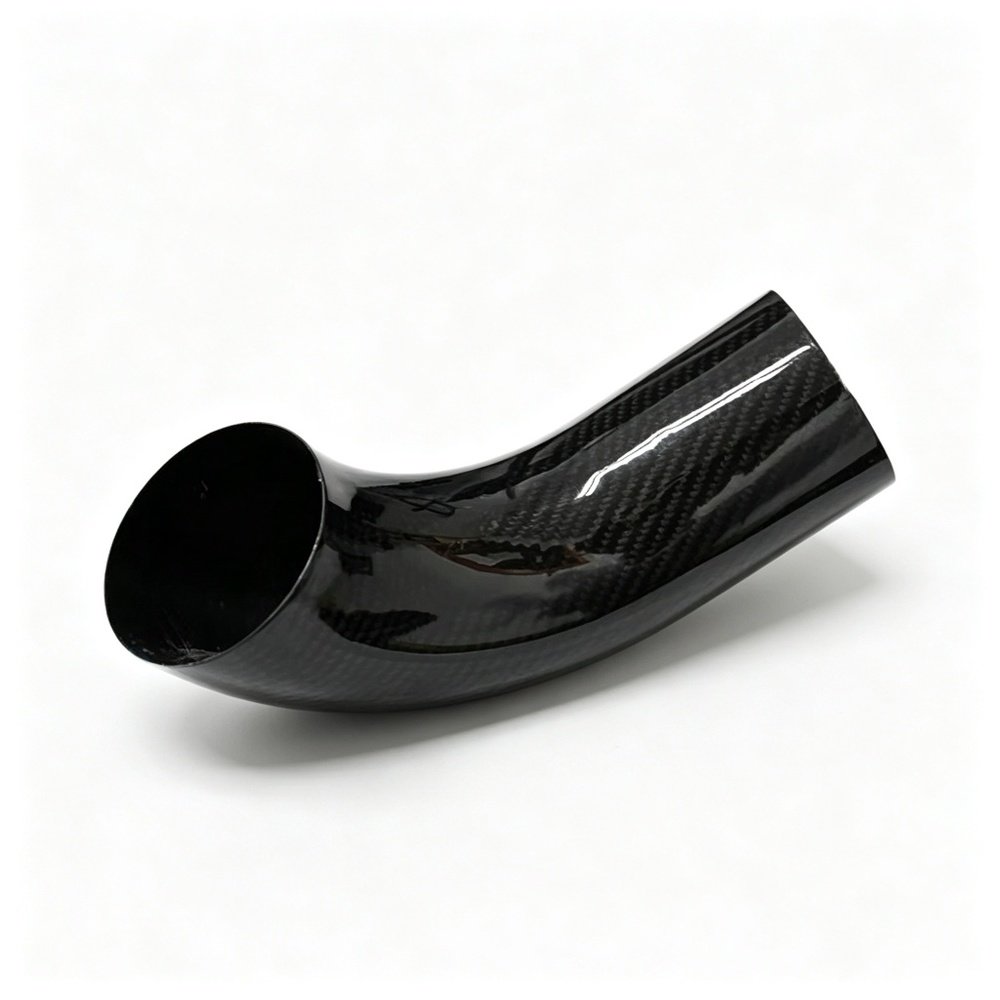
Curved carbon fiber elbow tube showing the bend and trimmed ends

Custom Carbon Fiber Elbow Tubes

A curved composite tube for an assembly that turns a corner. The published example describes curved-mandrel forming followed by curing and trimming.

Drawing and inspection Call out bend angle, radius, end alignment and the dimensions used to check the assembled fit.

Composite frame plates
License plate frames
Molded cover
Molded cover
Composite shell
Composite shell
Molded trim pair
Molded trim pair
Mirror covers
Mirror covers
Composite panel
Composite panel
Curved molded cover
Curved molded cover
Slotted composite plate
Paddle blades
Paddle blades
Sports paddle
Sports paddle
Carbon-fiber tubes
Carbon-fiber tubes

Carbon Fiber Forming Processes

Tooling is prepared for the part design. Roll wrapping, compression molding and autoclave curing are different process routes selected for the component geometry and laminate requirements.

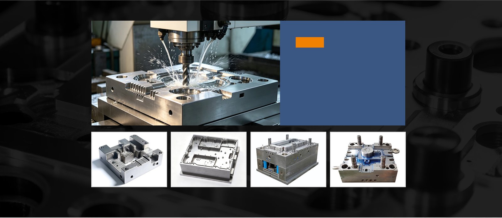
Tooling process example
Machined mold example 1
Machined mold example 2
Mold assembly example 3
Mold assembly example 4

Tooling Design and Machining

CAD/CAM data guides the machining of steel or aluminum tooling to the component geometry and drawing requirements.

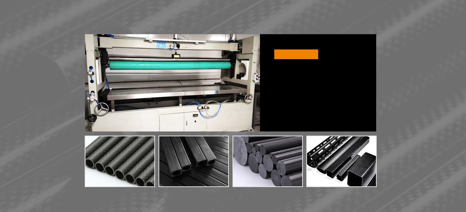
Roll-wrapping equipment
Round tubes
Rectangular tubes
Solid rods
Profiles

Roll-Wrapping for Tubes and Profiles

Roll wrapping forms carbon-fiber tubes and profiles. Fiber orientation and wall thickness are defined for each component.

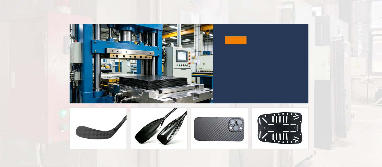
Compression molding equipment
Stick blade example
Paddle blade examples
Phone cover example
Slotted plate example

Prepreg Compression Molding

Prepreg sheets are laid into matched molds and cured under controlled pressure and temperature to form the component.

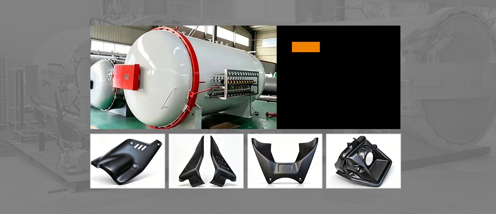
Autoclave curing equipment
Molded cover example 1
Molded cover example 2
Molded panel example 3
Molded housing example 4

Prepreg Lay-Up and Autoclave Curing

Prepreg plies are arranged in the required orientations, vacuum-bagged and cured in an autoclave under project-specific temperature and pressure conditions.

Choose a Carbon Fiber Process by Part Shape

Start with the part shape and the features that control fit. These are routes to review. The drawing, laminate and tooling requirements determine the final choice.

Part ShapeRoute to ReviewDrawing InputsInspection Focus
Tubes & ProfilesTube examplesConsider roll wrapping for straight tubes and suitable profiles. Review curved tooling for bends.Cross-section, length, wall thickness and lay-up. For bends, include angle, radius and end orientation.Straightness or bend geometry, trim planes and mating fit.
Molded ShellsMirror housing exampleCompare matched-tool compression molding with lay-up and autoclave curing.3D surfaces, laminate thickness, tool side, trim line and mounting interfaces.Surface profile, edge condition, mounting fit and appearance requirements.
Flat PlatesFrame plate exampleReview the laminate construction, then consider CNC profile routing from plate stock.Profile, thickness, ply orientation and any flatness or edge requirements.Thickness, flatness, contour and cut-edge condition.
Parts with Holes or Mounting FeaturesFoot pedal plate exampleReview drilling and countersinking or slotting after forming.Hole and slot sizes, locating datums, fastener details and fit requirements.Feature position, hole size, edge breakout and fit with the mating part.
Share Your Drawing for Process Review

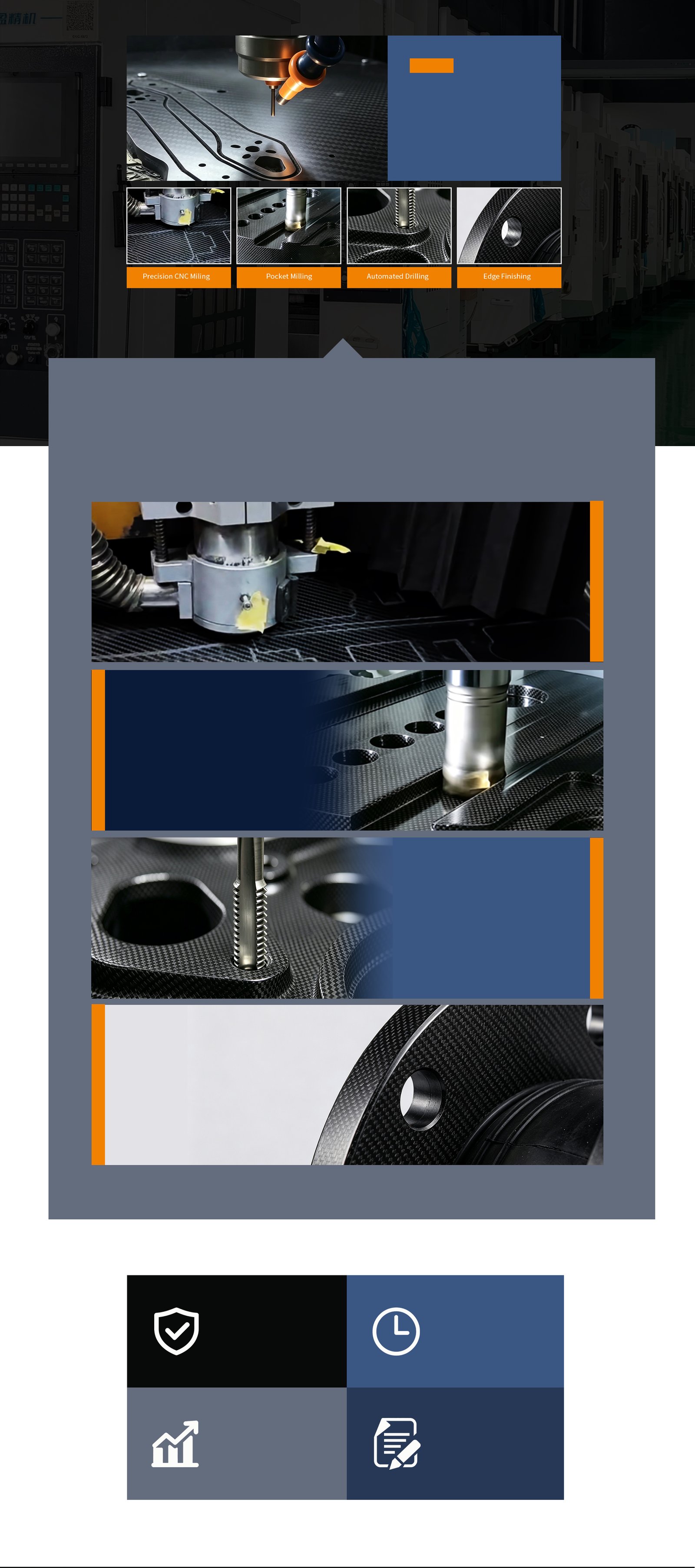
Multi-Axis CNC Finishing

Composite-specific diamond tooling supports profile routing, slotting, drilling, and countersinking with clean, controlled edges.

Composite CNC machining process illustration
CNC milling illustration
Pocket milling illustration
Drilling illustration
Edge finishing illustration

Composite machining process illustrations

Profile routing process illustration

High-Precision Profile Routing

Profile routing and contour finishing for structural frames, industrial backplates, and adapter panels.

Drilling and countersinking illustration

Precision Drilling & Countersinking

Clean mounting points and flush fastener seating while reducing micro-cracking and edge breakout risks.

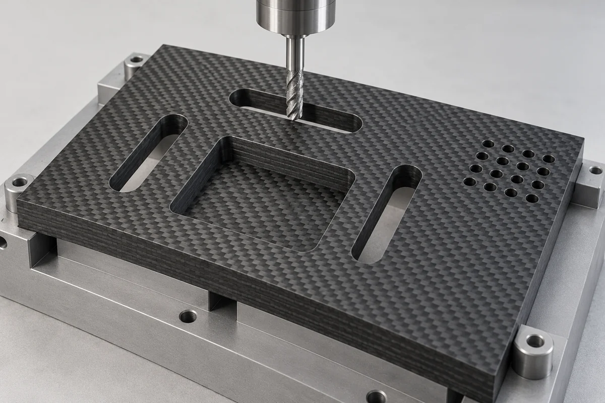
Process illustration of slots, a recessed pocket and ventilation holes in a carbon-fiber laminate panel.
Process illustration

Intricate Slotting & Pocket Milling

Internal cutouts, interlocking slots, and ventilation patterns for mechanical assemblies and enclosures.

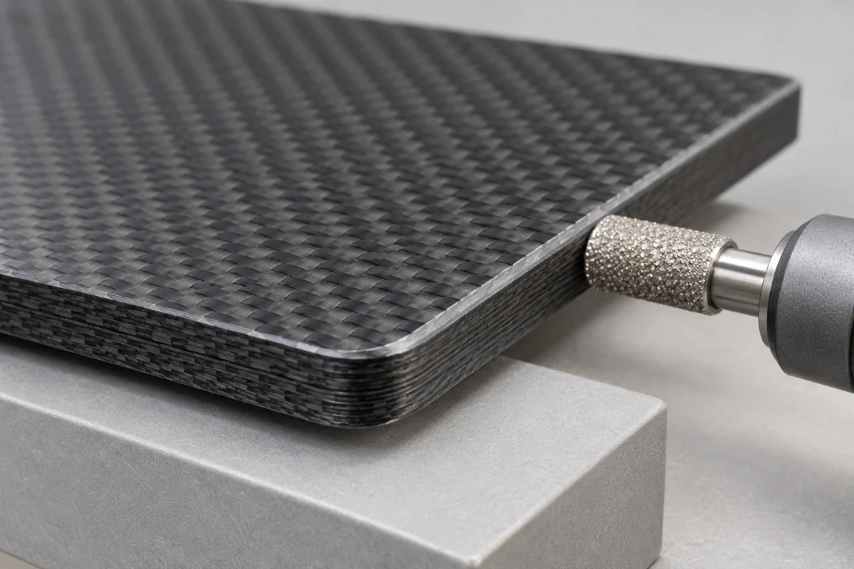
Process illustration of a smooth conditioned edge and laminate layers on a carbon-fiber panel.
Process illustration

Advanced Edge Conditioning

Deburring and calibrated edge treatments for clean presentation while preserving laminate integrity.

Technical Specifications and Process Notes

CAD reviewPDF/DXF/STEP
Mold designCustom matched tooling
Material3K/UD/twill prepreg
FinishingCNC drilling / routing
InspectionCMM /visual /fit check
Molding pressureProject-specific
TemperatureProcess-specific
ToleranceDrawing review required
Surface finishDefined by requirement

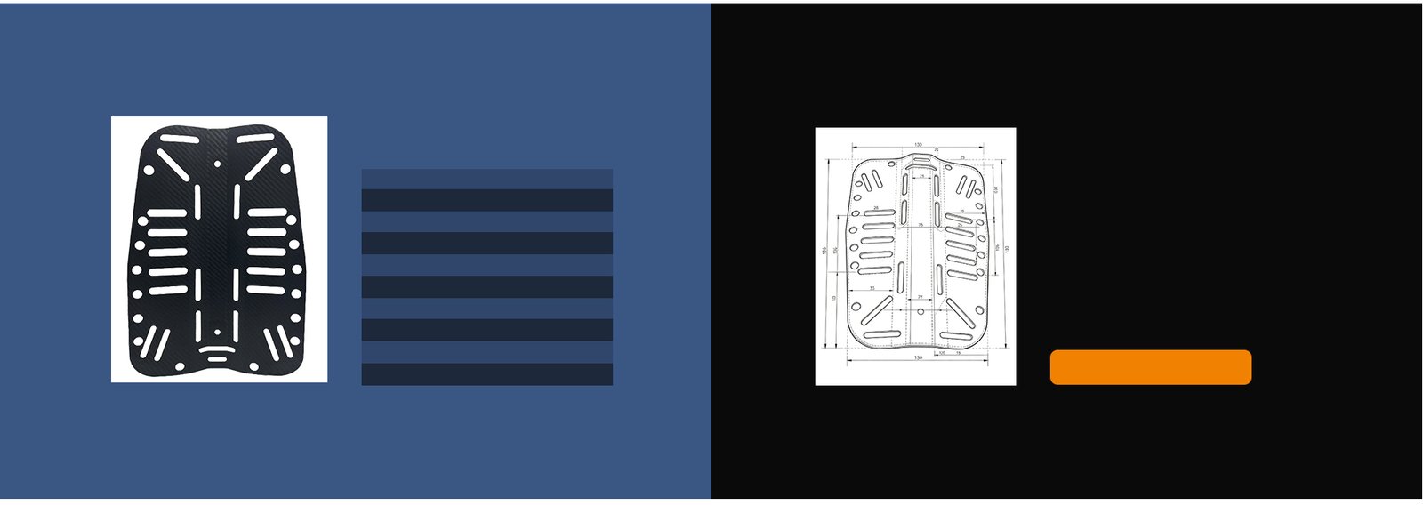
Component and drawing examples. Manufacturing dimensions, tolerances, molding conditions and surface requirements are defined for each project and confirmed from the approved drawings.