
Solar Cable Clamp
Custom clips for cable routing on PV frames and rails
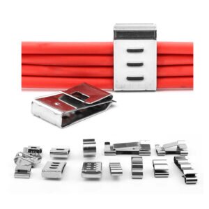
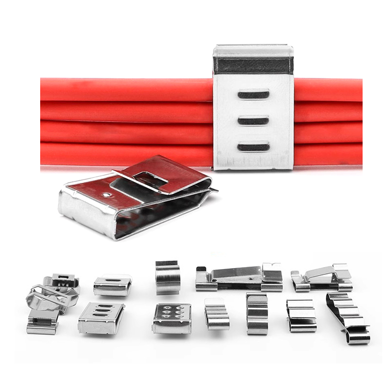
A solar cable clamp positions one or more cables at a specified location on a PV module frame or mounting rail. The image shows clips holding red cables above a selection of clip geometries. Cable capacity and mounting fit are reviewed using the cable dimensions and the supporting profile drawing.
Material options include stainless steel (SUS304/SUS316) and engineering plastic. For metal clips, specify the material condition and required spring behavior. For plastic versions, define the resin grade and UV exposure requirements. Grade, thickness and geometry are selected for the particular clamp rather than assumed to provide the same retention or environmental performance.
Cable and Mounting Interfaces
- Cable Capacity: Provide the cable count and outside diameter, including the jacket.
- Mounting Profile: Show the frame or rail section, flange thickness and the location available for the clip.
- Clip Configuration: Clip-on, snap-fit and multi-cable versions are assessed against the specified profile and cable arrangement.
- Contact Edges: Define the edge condition and cable-contact geometry needed by the design.
- Retention Requirements: State the target holding force, loading direction and test conditions for the assembled cable and clip.
Dimensions and Spring-Force Requirements
Identify critical dimensions and agree the inspection method for the selected material and design. Review the figures below against the drawing. For spring-force consistency, define the nominal force, deflection or measurement position, fixture and acceptance conditions.
- Thickness Tolerance: ±0.02–0.05 mm
- Width/Length Tolerance: ±0.05–0.10 mm
- Clamping Range Tolerance: ±0.10 mm
- Spring Force Consistency: ±10%, subject to the agreed target force and test conditions
- Surface Roughness: Ra ≤ 1.6–3.2 μm
- General Dimensional Tolerance: ±0.05–0.10 mm
Manufacturing and Finish
Metal clip designs may use stamping, laser cutting and forming. A plastic version requires a separate injection-molding and material review. Any heat treatment must be specified for the selected alloy, material condition and manufacturing route.
- Stamping or laser cutting of the blank and profile
- Bending and forming of the specified clip geometry
- Deburring and finishing of the edges and cable-contact areas
- Passivation or polishing for suitable metal versions
- UV-stabilized material selection for plastic versions, with validation requirements defined by the project
- Inspection of agreed dimensions; spring-force and durability verification requirements to be specified separately
Cable-Management Applications
Clip designs can be reviewed for rooftop or ground-mounted PV cable routing in residential, commercial and solar-farm projects. Provide the exposure conditions and mounting arrangement so the material and fit requirements can be assessed. Installation method and retention are confirmed for the selected clip and assembly.
Specify Your Cable Clamp
Send the clip and mounting-profile drawings, cable details, material specification and quantity. Include finish, marking, prototype and inspection requirements, together with any environmental or retention validation criteria.
Explore our sheet metal fabrication processes or discuss your solar cable clamp project. You can also contact eleven@grancen.com directly.
Reviews
There are no reviews yet.