
Solar Panel Mounting Clamp
Custom clamp profiles for specified module frames and rails
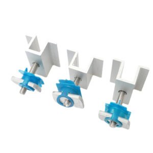
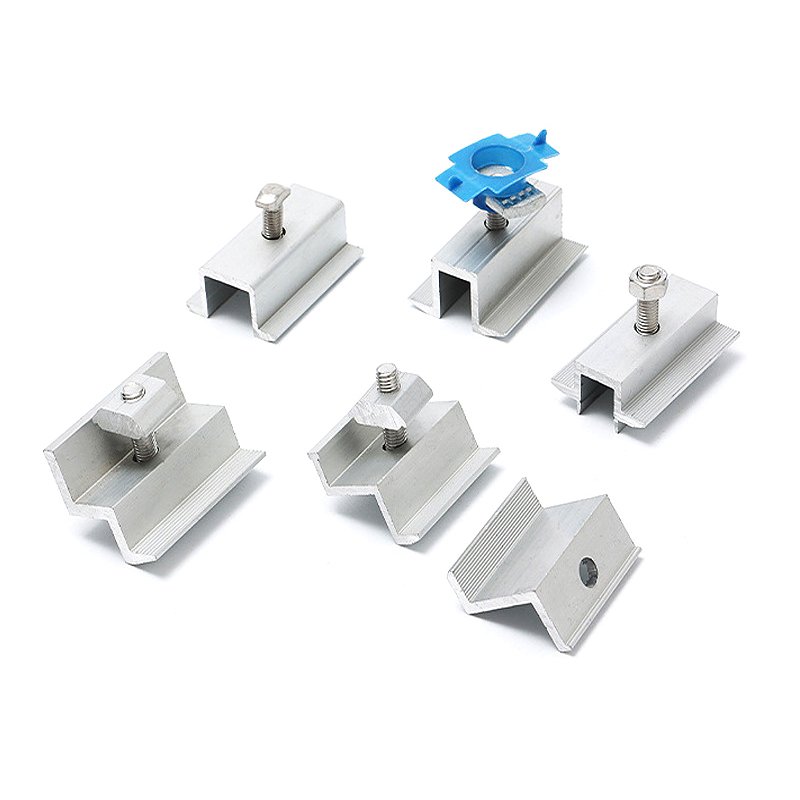
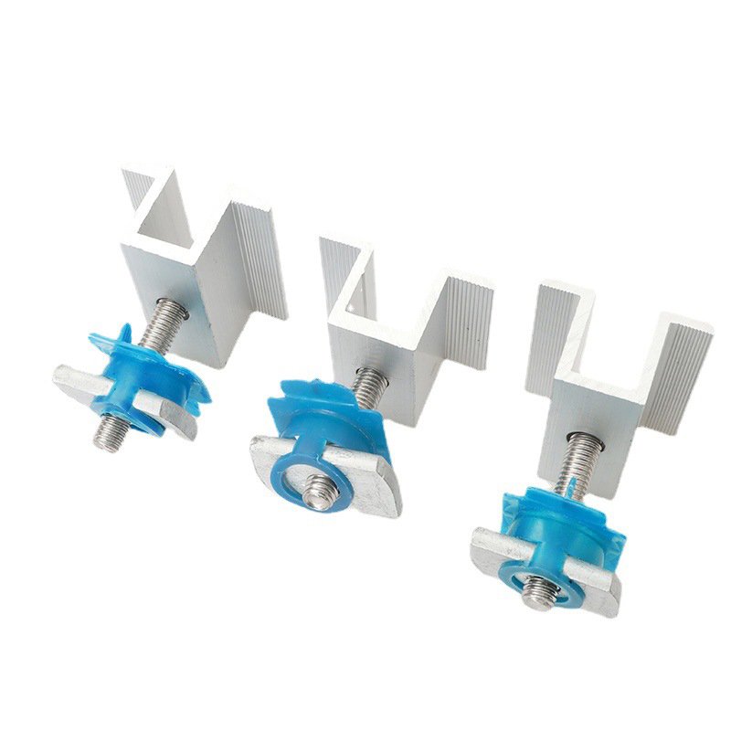
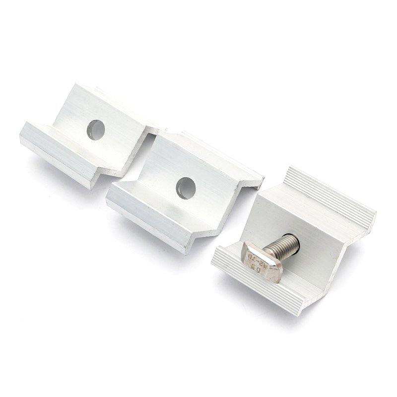
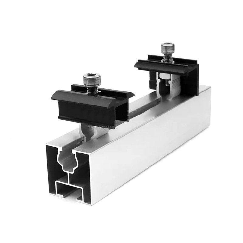
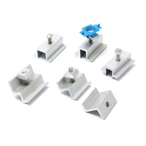
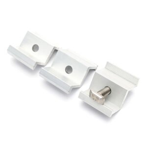
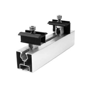
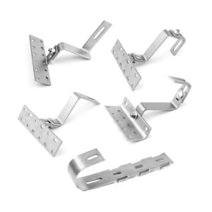
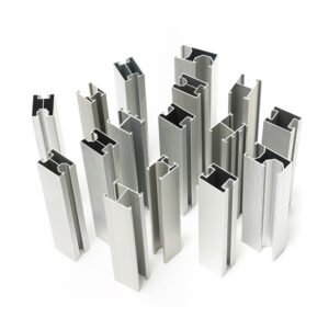
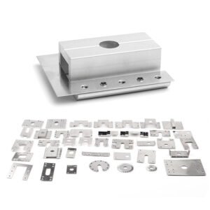
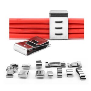
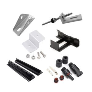
A solar panel mounting clamp forms part of the connection between a PV module frame and its mounting rail. The pictured stepped clamps have bolts and blue retaining pieces. Other product views show profile variants and a clamp-to-rail assembly. The selected configuration is reviewed against the frame, rail and fastening drawings.
Material options include aluminum alloy (6061/6063) and stainless steel (SUS304/SUS316). Specify the grade, material condition and finish for the clamp body and any custom fastening parts. These options are assessed against the geometry, environment and assembly requirements.
Frame and Rail Fit
- Clamp Type: Define the required mid-clamp, end-clamp or adjustable configuration.
- Module Interface: Provide the frame section, clamping height, contact area and permitted contact conditions.
- Rail Interface: Show the rail profile, slot geometry and mating fastening components.
- Fastening Details: Specify threads, holes, component stack and assembly clearances.
- Acceptance Requirements: Define the required fit, retention and module-frame contact verification for the assembled connection.
Wind, snow, thermal movement and other structural conditions are defined by the mounting-system design. Supply the applicable assembly and load-related acceptance requirements with the clamp drawing.
Tolerance & Dimensions
Identify the dimensions that control clamping height, profile engagement and mounting alignment. Confirm the following figures for the selected material, size, process and finish before agreeing the feature-specific inspection limits.
- Clamping Range Tolerance: ±0.10 mm
- Thickness Tolerance: ±0.05–0.10 mm
- Hole Position Tolerance: ±0.05 mm
- Flatness: ≤0.3 mm
- Surface Roughness: Ra ≤ 1.6–3.2 μm
- General Dimensional Tolerance: ±0.05–0.10 mm
Clamp Manufacturing
The body and fastening requirements determine the manufacturing route. Extruded aluminum profiles are reviewed for the specified section and tooling; machined features are defined separately on the drawing.
- Aluminum extrusion for suitable clamp-body profiles
- CNC milling, drilling, slotting and tapping
- CNC turning and threading for custom fastening parts where required
- Deburring and surface finishing
- Anodizing for suitable aluminum parts, or passivation for suitable stainless steel parts
- Specified coating, identification or logo marking
- Assembly of the specified clamp body and fastening components
- Inspection of agreed dimensions, interfaces and appearance
Mechanical verification criteria, including the required frame contact and retention conditions, are specified for the complete connection.
PV Mounting Applications
Clamp designs can be reviewed for residential, commercial, industrial or ground-mounted PV projects. Provide the actual module-frame, rail and connection drawings for the selected mounting system.
Specify Your Clamp
Send the clamp drawing with the module-frame section, rail profile and fastening details. Include material grades, finishes, quantity, critical fits and any prototype or assembly-verification requirements.
Explore our CNC machining processes or discuss your mounting clamp project. You can also contact eleven@grancen.com directly.
Reviews
There are no reviews yet.