

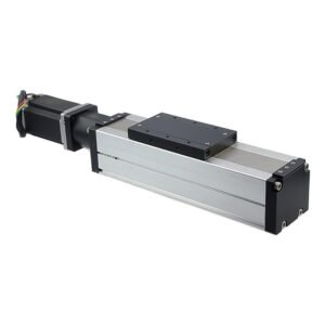
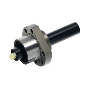
An end mount plate provides an attachment face at the end of a linear stage or motor-driven assembly. Define the motor pilot, shaft clearance and plate locating surfaces so the motor and drive interfaces can be reviewed together.
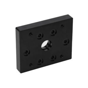
The example shows a rectangular plate with a central bore and counterbored mounting holes. Mark the required hole form and fastener head on the drawing so the installed clearance is clear.
Motor and Stage Interfaces
- Motor: Supply the exact model and drawing for a NEMA 23 or other motor. Include the flange pattern, pilot diameter, shaft projection and connector clearance.
- Center Bore: Specify whether it locates the motor pilot or provides clearance for the shaft and coupling. Dimension the fit or clearance and identify the datum.
- Stage: Provide the base bolt pattern, locating face and any alignment features. Include access for installation and tools.
Fastener Seats and Threads
For a counterbore, specify the recess diameter and depth. For a countersink, define the cone angle and opening diameter. Use the required screw head and seating condition to define protrusion or flushness. Mark clearance holes, any ISO metric threads, thread depth and the approach side.
Aluminum Grade and Finish
Review 6061-T5 aluminum against the required material specification and temper. Specify black anodizing where required, with masking or dimensional allowances for locating faces, bores and threaded holes. Explore our CNC machining processes.
Thickness, Hole Locations and Inspection
- Thickness: Review the 12 mm ±0.05 mm reference against the installed stack and shaft engagement.
- Flatness: For a ≤0.03 mm reference, identify the mounting face, inspection area and free or installed condition.
- Hole Locations: Where the drawing uses coordinate tolerances, confirm the applicable limit from the ±0.02–0.05 mm reference. If it uses geometric position, provide the datum scheme and positional callout.
- Other Dimensions: Use ±0.05 mm as a reference for the individual features identified on the drawing.
Request an End Mount Plate Quote
Send the plate and assembly drawings, motor model, shaft and coupling details, material, finish, quantity and inspection requirements.
Discuss your end mount plate project or email eleven@grancen.com.
Reviews
There are no reviews yet.