
CNC quality inspection begins before a finished part reaches a measuring instrument. For an international sourcing project, the most reliable inspection plan connects the released drawing, the datum structure, the manufacturing sequence and the intended function of the component. When those elements agree, suppliers and buyers can discuss results using the same technical reference.
A long list of dimensions does not automatically create an effective quality plan. The useful question is which features control assembly, alignment, sealing, movement or load transfer, and how those features can be measured consistently. This guide explains how purchasing, engineering and quality teams can prepare that information for a custom CNC project.
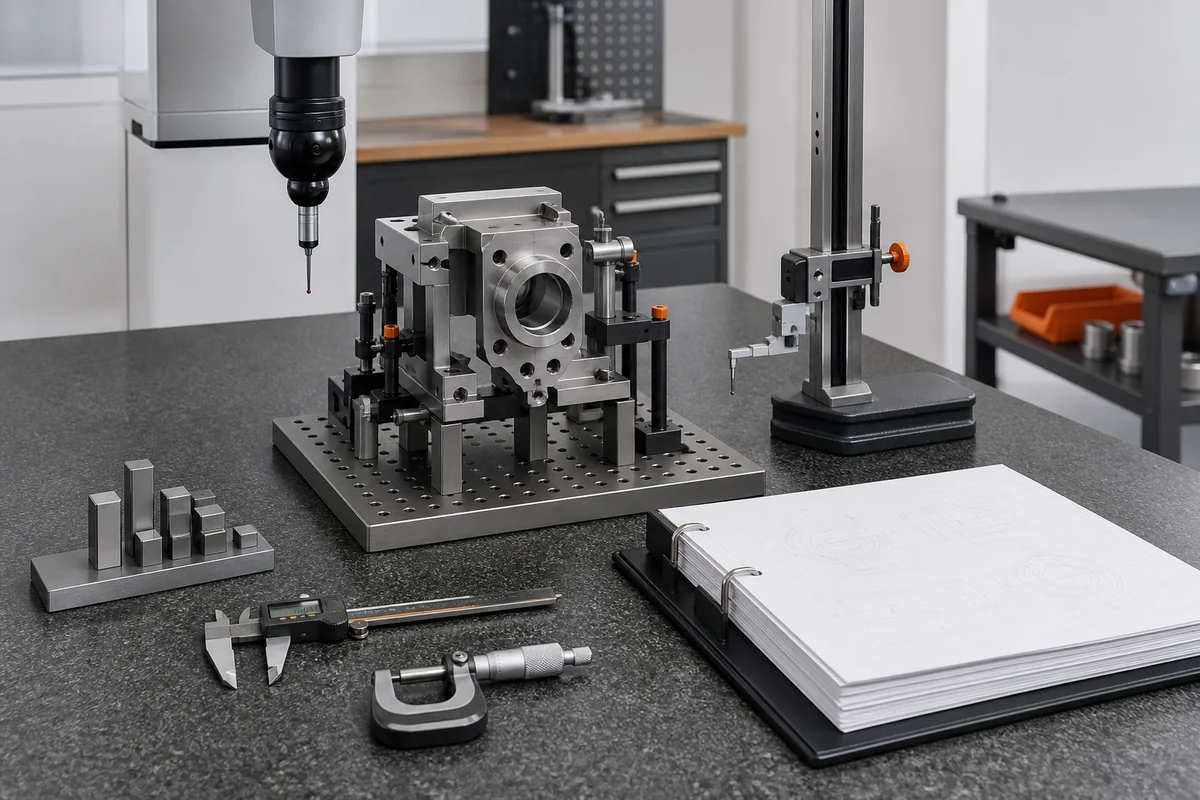
Start With a Controlled Drawing Package
The inspection plan should reference the same revision used for quotation and production. A 3D model communicates geometry, but the 2D drawing normally defines datums, tolerances, surface-finish notes, threads and reporting requirements. If the two files conflict, the RFQ should state which document controls and the issue should be resolved before production approval.
- Use a clear part number and revision on every controlled file.
- Identify critical or key characteristics without marking every dimension as critical.
- State whether dimensions apply before or after coating, heat treatment or another secondary operation.
- Define any required inspection report, sample size or first-article review in the quotation scope.
This preparation helps prevent a common sourcing problem: a part may match isolated dimensions but still fail to fit because the drawing and inspection approach did not control the relationships that matter.
Use Datums to Connect Design and Measurement
Datums establish the reference framework for locating and orienting a part. They should reflect how the component interfaces with its assembly rather than simply choosing the easiest surfaces to measure. A primary datum stabilizes the part, a secondary datum controls another direction, and a tertiary datum completes the setup. The exact scheme depends on part geometry and function.
Functional Datums
A mounting face, locating bore or pin pattern may provide a more useful functional reference than an external cosmetic surface. When the datum structure follows the assembly, position, perpendicularity and profile results are easier to interpret in relation to actual use.
Manufacturing and Inspection Access
Design intent remains the priority, but the datum plan should also consider workholding and probe access. Deep cavities, interrupted surfaces, flexible walls or features hidden after assembly can require a different measurement strategy. Discussing access during DFM review can expose these risks before the inspection method is fixed.
Match the Measurement Method to the Feature
No single instrument is ideal for every feature. Calipers and micrometers can support straightforward checks, while height gauges, bore gauges, optical systems, hardness equipment or coordinate measurement resources may be appropriate for other requirements. The selected method should consider feature type, tolerance, surface condition, access and the repeatability needed for the agreed inspection scope.
Plan for Complex Relationships
True position, profile and relationships between features require more than checking individual sizes. The setup must recreate the drawing datum system and avoid distortion from clamping. Thin sections, long parts and temperature-sensitive materials may also need controlled handling so the measurement represents the part rather than the fixture.
Define an Inspection Scope That Matches Risk
Inspection effort should be proportional to part risk and the agreed commercial scope. A prototype may require a detailed dimensional review to support design learning. A repeat order may use an approved control plan focused on critical features, process checks and final verification. The appropriate frequency depends on the drawing, manufacturing process, quantity and buyer requirements.
- Confirm incoming material documentation when it is part of the order requirement.
- Verify setup-critical features during machining rather than waiting until final inspection.
- Separate dimensional, visual, functional and documentation checks.
- Define how nonconforming results will be contained, reviewed and communicated.
- Agree whether records are retained internally or supplied with the shipment.
Material or dimensional reports can be defined according to agreed project requirements. They should not be assumed automatically; include them in the RFQ so the supplier can plan the work and quotation correctly.
Review Finishing, Threads and Edge Conditions
Secondary operations can change dimensions or measurement access. Coating thickness may affect mating features, heat treatment may influence geometry, and polishing can alter an edge or surface. Drawings should identify masked areas, post-finish dimensions and cosmetic zones where appearance criteria apply.
Threads, inserts, cross-holes and deburring requirements also deserve explicit checks. A thread gauge may confirm thread acceptance, while the drawing should state whether insert installation or functional assembly verification is required. Edge notes should be specific enough to avoid both unsafe burrs and excessive edge break.
Make Reports Easy to Review
An inspection report is most useful when each result maps clearly to the released drawing. Ballooned characteristics, drawing revision, unit of measure, nominal value, acceptance limits and recorded result create a traceable review path. Where a feature is measured by a special setup or calculation, a short method note can prevent later confusion.
International teams should also agree on language, units and file format. Clear records reduce back-and-forth between engineering, procurement and quality teams and help both sides address open points before shipment.
Prepare Quality Requirements for Your CNC RFQ
Before requesting a quotation, confirm the drawing revision, datum scheme, critical features, finish condition, sampling expectation and documentation scope. Share the assembly context when it helps explain why a relationship matters. Grancen can then review the available information together with the proposed machining route and raise focused DFM or inspection questions.
Explore Grancen’s CNC machining services and manufacturing background. When your drawing package is ready, send the project through the approved request-a-quote form for an initial review.