
A strong CNC machining result begins with a drawing that connects function, manufacturability and inspection. Design for manufacturability (DFM) helps engineering and sourcing teams identify avoidable risk before material is cut.
This practical CNC machining design guide explains how to prepare custom parts for a productive engineering review. The objective is not to simplify every component. It is to keep the features that protect performance while removing unnecessary constraints that can complicate tooling, setup, measurement or finishing.
Start with Function and Inspection Requirements
Before changing geometry, identify what the part must do. Mark mating faces, bearing locations, sealing areas, alignment features and cosmetic surfaces. Also identify which dimensions are critical to assembly or performance. This gives the manufacturing team a clear basis for evaluating process options and inspection methods.
A controlled 3D model defines nominal geometry, while a 2D drawing can communicate tolerances, threads, datums, finishes and acceptance notes. Supplying both reduces ambiguity. STEP, IGES, SolidWorks, DXF, DWG and PDF are common review formats, but the drawing revision used for quotation and production should always be clear.
Design Geometry for Tool Access and Stability
Use practical internal corner radii
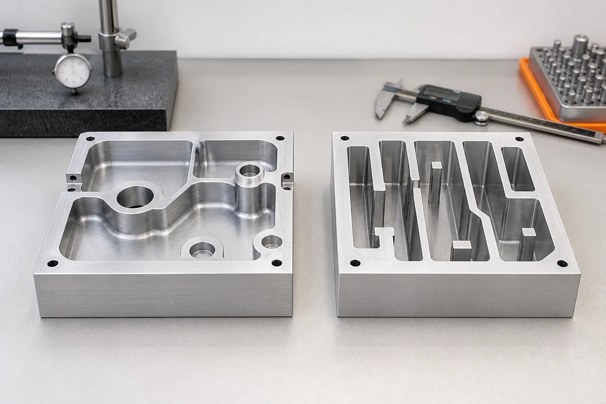
Rotating cutters naturally leave a radius in internal corners. A sharp internal corner may require a different process, smaller tooling or extra operations. When the design allows it, a larger internal radius can provide more room for a stable cutter and a smoother tool path. Keep truly sharp corners only where they serve a defined function, then discuss how they will be produced and verified.
Review deep pockets and thin walls
Deep, narrow pockets can restrict tool access and chip removal. Tall, thin walls may move under cutting forces or during unclamping. Where function permits, reduce unnecessary depth, open access from another direction, add supportive transitions or divide the feature into a separate component. If a slender wall is essential, flag it during the RFQ so workholding, sequence and inspection can be considered together.
Plan Holes, Threads and Edge Features
Holes are easier to plan when their diameter, depth, tolerance and purpose are stated. Standard drill sizes can simplify tooling where the exact size is not functionally critical. Through holes may offer easier access than blind holes, but sealing, appearance and assembly needs may require a blind feature. Provide enough distance from edges and neighboring walls for machining and inspection access.
For threads, specify the thread standard, size, class where needed and required engagement. Separate the useful thread depth from the total drilled depth. Excessively deep threading may add work without improving the joint. Cross holes, undercuts, deburring requirements and break-edge notes should also be defined because these details affect the operation sequence and final handling.
Apply Tolerances from Functional Datums
A blanket tight tolerance across the drawing can increase process and inspection demands without improving the product. Instead, relate critical features to functional datums and apply limits where they protect fit, motion, sealing or alignment. Noncritical dimensions can use suitable general tolerances agreed for the project.
Geometric controls such as position, runout, perpendicularity or profile are most useful when they describe how the part functions. The datum scheme should be repeatable in both machining and inspection. If multiple tightly controlled features depend on different setup directions, an engineering review can determine whether the process plan and measurement strategy are aligned.
Choose Material and Finishing Early
Material grade, starting stock and heat-treatment condition can influence machining behavior, distortion risk and sourcing. State the full material specification rather than only a broad family name. If an approved alternative may be considered, identify the properties or standards that must remain unchanged.
Finishes should be reviewed with the geometry and tolerance plan. Coating, plating, anodizing, polishing or blasting may affect selected surfaces, edges or mating conditions. Mark cosmetic zones, masking needs and surfaces that must remain conductive or uncoated. Agree whether dimensional requirements apply before or after finishing.
Build Inspection into the DFM Review
Inspection is more effective when the drawing states what must be verified and why. Critical dimensions, functional relationships, surface requirements and any requested documentation should be confirmed during quotation. Depending on the feature and agreed scope, measurement may use calipers, micrometers, gauges, optical equipment or coordinate measurement methods where applicable.
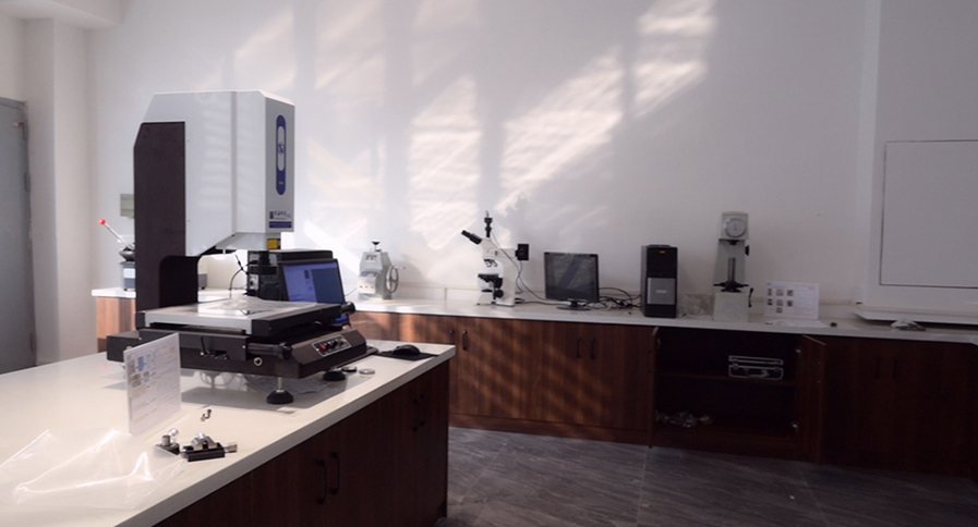
A feature that cannot be reached or referenced reliably may be difficult to inspect consistently. Reviewing measurement access, datum simulation and required records before production helps connect the drawing to a realistic quality plan.
CNC Machining RFQ Checklist
- Controlled 3D model and 2D drawing with the same revision
- Material grade, condition and any approved alternatives
- Order quantity and whether the request is prototype or repeat production
- Functional datums, critical dimensions and geometric controls
- Threads, inserts, edge breaks and deburring expectations
- Surface finish, coating, masking and cosmetic requirements
- Inspection criteria, records and packaging needs
Move from DFM Review to a Controlled Manufacturing Plan
Good DFM is a technical conversation, not a universal set of dimensions. The appropriate choice depends on geometry, material, quantity, finish and the evidence the buyer needs. Review Grancen CNC machining capabilities and the related guide to our CNC manufacturing process for the path from inquiry through inspection and delivery coordination.
To request a manufacturability review, share the current model, drawing and project requirements through the existing Grancen inquiry route. The engineering team can then clarify open features and prepare a process proposal around the confirmed scope.