
Choosing a carbon fiber manufacturing method is not simply a question of finding the “best” process. The right route depends on part geometry, laminate architecture, surface expectations, tooling strategy, production quantity and the features that must be machined after curing. A process that suits a straight tube may be inefficient for a contoured cover, while a method that produces a detailed molded shell may add unnecessary tooling for a flat plate.
For overseas product teams, the practical goal is to match the manufacturing route to the drawing and application before tooling begins. This guide explains several methods used for custom composite parts and the questions that help a supplier review manufacturability. Grancen’s carbon fiber manufacturing service combines composite forming, tooling review and CNC post-machining within one drawing-based workflow.
Start With Geometry and Laminate Requirements
Manufacturing decisions should begin with what the part must do. Product teams should identify load direction, stiffness priorities, cosmetic surfaces, wall-thickness transitions, inserts, holes and assembly interfaces. Fiber orientation is especially important because a composite laminate is designed through the placement and direction of its reinforcement, not only through its overall thickness.
The drawing should also distinguish molded features from machined features. A hole that needs a controlled assembly position may be better created after curing, while a broad contour or rib may belong in the mold. Separating these requirements helps the supplier plan tooling, layup, cure and inspection as one connected sequence.
Roll-Wrapping for Tubes and Consistent Profiles
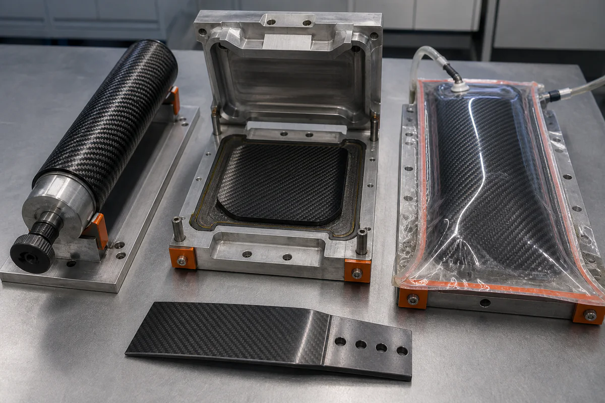
Roll-wrapping is commonly considered for tubes and other relatively consistent profiles. Carbon fiber prepreg is arranged around a mandrel according to the required laminate schedule, consolidated and cured, and then removed from the tool. The mandrel defines the internal geometry, while the ply layout influences axial, torsional and hoop behavior.
This route can be useful when the design needs a repeatable tubular form without the complexity of a deeply contoured matched mold. Important RFQ inputs include the profile, length, wall structure, end conditions, visible surface expectations and any holes or slots that will be added later. Product teams should avoid treating every tube as a simple commodity: local reinforcement, bonded inserts and end machining can materially change the process plan.
Matched-Die Compression Molding for Defined Shapes
Compression molding uses matched tooling to shape layered prepreg under controlled heat and pressure. It is well suited to components that need defined outer and inner surfaces, repeatable contours or integrated details that would be difficult to create from flat stock. The mold becomes a major part of the manufacturing system, so draft, radii, parting lines and demolding access should be reviewed early.
The process is not selected by shape alone. Laminate placement must remain compatible with the cavity, and abrupt section changes can make consolidation more difficult. A supplier may suggest adjusting a corner, splitting a feature or moving a precision interface to a post-machining operation. These recommendations are project dependent and should be resolved against the functional drawing before tooling is released.
Vacuum-Bagged Prepreg and Autoclave Curing
For contoured laminates, individual prepreg plies can be placed on a tool in planned orientations, enclosed in a vacuum-bagging stack and cured under a defined cycle. Vacuum helps consolidate the layup and manage trapped air, while the selected curing equipment and cycle depend on the material system and part requirements. Autoclave curing is one version of this approach; it should not be specified automatically when another controlled cure route can meet the actual engineering need.
This method gives engineers flexibility to tailor local ply orientation and reinforcement around load paths or attachment areas. It also makes workmanship planning important. Ply boundaries, bagging details, tool surface, material storage and cure records all affect repeatability. Buyers should provide the laminate specification or clearly state which decisions remain open for supplier review.
Tooling Connects Design to Repeatable Production
Composite tooling controls geometry, surface condition, demolding and the stability of the cure setup. Steel or aluminum tooling may be considered depending on size, thermal behavior, expected use and the production plan. The correct choice is project specific; the lowest initial tooling cost is not always the lowest-risk route when revisions, inspection access and repeat orders are considered.
A useful tooling review includes the 3D model, controlled 2D dimensions, laminate boundaries, datum strategy, cosmetic-side definition and anticipated post-machining setup. Tooling should be discussed together with the method, not after the manufacturing route has already been fixed.
Plan CNC Post-Machining Before the Part Is Cured
Cured carbon fiber parts often require routing, drilling, slotting, countersinking or edge conditioning. These operations create assembly features and final profiles that may be difficult to mold precisely. Composite-specific tooling and stable fixturing help control edge breakout, delamination risk and dimensional variation, but the setup depends on laminate support and datum access.
Designers should identify critical holes, mating surfaces and inspection datums before the layup and tool are finalized. That allows the manufacturing team to reserve fixture access and avoid cutting through poorly supported features. When a component combines molded geometry with tight mechanical interfaces, Grancen can review the composite route together with its CNC machining requirements.
What to Include in a Carbon Fiber RFQ
- Controlled 3D and 2D files, with revision status.
- Application context and the surfaces or interfaces that are functionally critical.
- Preferred material system, weave appearance or laminate schedule, if already specified.
- Expected quantity range and whether the request is for prototype review or repeat production.
- Cosmetic-side, edge, insert, bonding and post-machining requirements.
- Inspection expectations, assembly references and packaging considerations.
- Open decisions that the supplier should evaluate during DFM review.
Select the Method as Part of the Whole Workflow
Roll-wrapping, matched-die compression molding and vacuum-bagged prepreg curing solve different geometry and laminate problems. The most reliable selection comes from reviewing material, tooling, cure, machining and inspection together. If you are preparing a custom composite project, send your drawings and requirements to Grancen for an initial manufacturing review.