
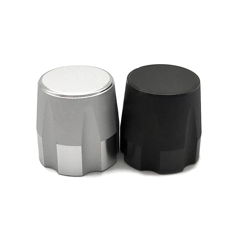
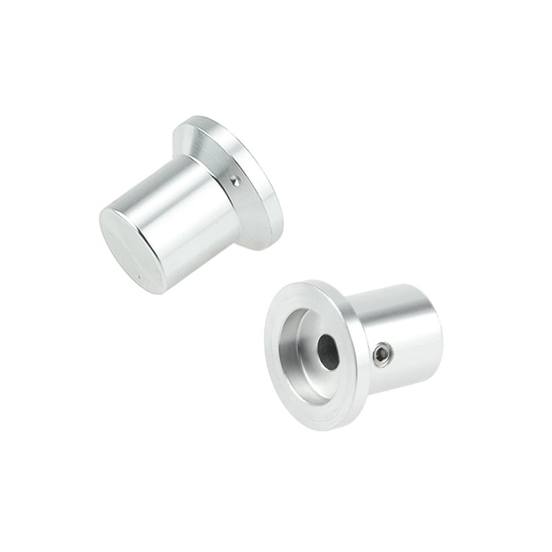
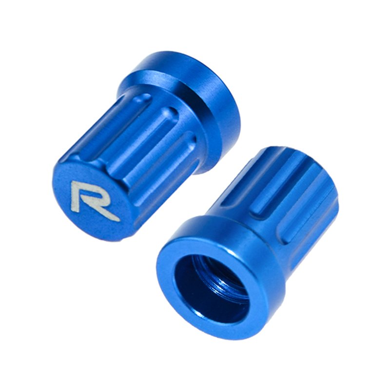
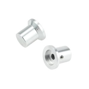
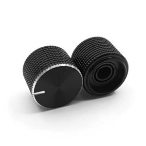
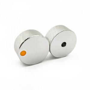
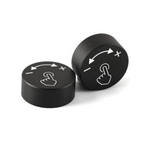
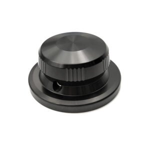
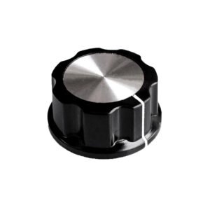
D-shaft control knobs provide a hand-operated interface for potentiometers and rotary encoders used in control panels. The knob bore must match the shaft profile, with the flat and any indicator marking positioned to suit the assembly.
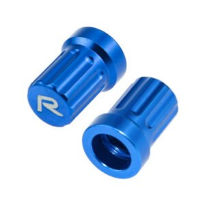
Fit, Mounting and Indicator Alignment
- Shaft interface: Provide the shaft diameter, flat dimensions, bore depth and engagement length on the mating drawing.
- Retention method: Select a push-fit or set-screw design. For a push-fit version, define insertion and pull-off requirements. For a set-screw version, specify the screw details and tightening requirements.
- Indicator position: Define the orientation of the shaft flat relative to the pointer, indicator line or printed scale.
- Body and panel clearance: Specify the knob diameter, height, skirt and space around adjacent controls.
For audio equipment, musical-instrument controls and instrumentation, include the operating-feel and adjustment requirements for the complete control assembly.
Material and Finish Options
Materials for project review include ABS, PC, aluminum alloy and hybrid constructions with a plastic body and metal cap. Specify the material grade, color, body and cap details, and the appearance sample where applicable.
Finish options include matte, gloss, anodized, coated, textured or specified soft-touch surfaces, selected to suit the material. Define smooth, fluted or knurled grip features on the drawing, together with any indicator line, scale or logo artwork.
Dimensions and Inspection Requirements
Mark the critical features and datum references on the drawing. The following tolerance figures require confirmation for the selected material, nominal size and manufacturing route before they are used as acceptance criteria.
- Outer diameter tolerance: ±0.05–0.10 mm
- D-shaft bore tolerance: ±0.01–0.02 mm for a specified broached bore, subject to feature and material review
- Flat alignment accuracy: ±0.5°
- Concentricity: ≤0.03 mm
- Surface roughness: Ra ≤ 1.6–3.2 μm
- Dimensional tolerance: ±0.05–0.10 mm
Specify the nominal bore diameter and flat geometry separately, with a tolerance for each critical feature. Define the flat-to-indicator reference, the features used to assess concentricity, and one roughness acceptance limit for each relevant surface. Agree on the inspection method and records during project review.
Manufacturing and Assembly Review
The body, shaft interface, inserts and cap are reviewed separately to select the production route. Depending on the construction, this may include injection molding, CNC turning or machining, broaching of the specified bore, surface finishing, and pad printing or laser marking.
Confirm the required inserts, caps and fastening parts, along with any prototype, appearance-sample or assembly checks. Inspection covers the agreed dimensions, shaft fit and indicator orientation.
Request a Custom D-Shaft Knob
Send the knob and mating shaft drawings, mounting method, material, finish, indicator artwork and quantity. Highlight critical fits and any sample or inspection requirements so the part can be reviewed against its intended assembly.
View our CNC machining processes or send your D-shaft knob requirements. You can also email eleven@grancen.com.
Reviews
There are no reviews yet.