
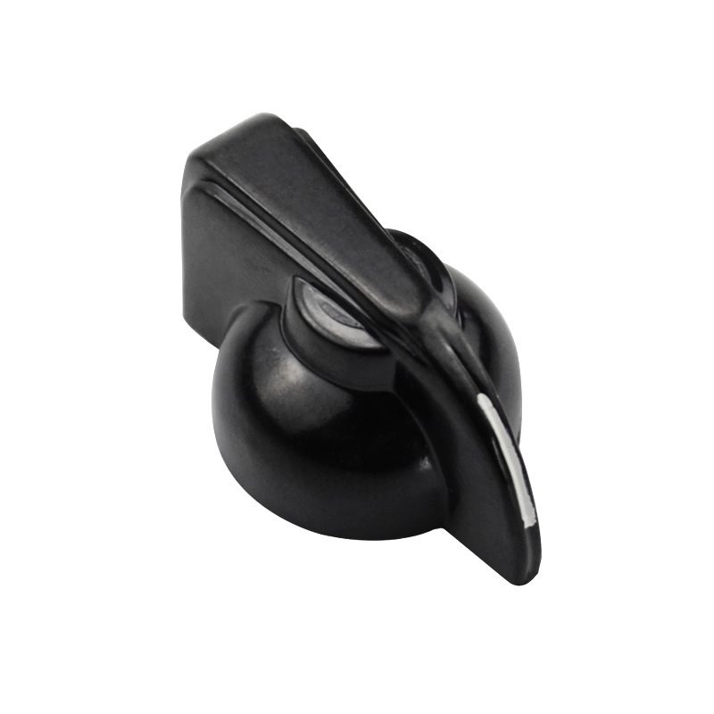
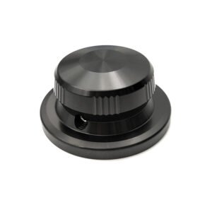
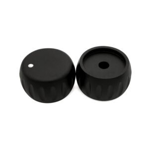
A chicken head knob uses an extended pointer to show its position against a control panel. The pictured black knob has a raised tapered pointer and a white indicator line. Define the pointer’s angular position relative to the shaft interface and the panel markings when specifying the part.
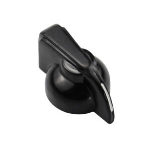
Engineering-plastic options include ABS or nylon, with an optional brass insert where the design requires one. Specify the resin grade, insert details and finish on the drawing. The selected material and mounting configuration need to be reviewed together for the intended control assembly.
Shaft Interface and Pointer Position
Specify the bore profile to match the actual control shaft, including the flat geometry for a D-shaped shaft or the spline profile for a splined shaft. Define the retention method separately, with set-screw fastening where specified. Supply the shaft drawing or a dimensioned sample with the knob requirements.
- Shaft Fit: Define the bore size and profile, engagement depth and fit requirements. Include the flat dimensions and orientation for a D-shaft, or the spline profile for a splined shaft.
- Fastening: For a set-screw design, specify the screw, thread, hole position, access and assembly conditions. Define the brass-insert interface if an insert is selected.
- Pointer and Panel Clearance: Show the pointer orientation, knob envelope, panel clearance and spacing to adjacent controls. Provide the panel scale or marking artwork where alignment is important.
Material, Molding and Finish
The production route is reviewed from the selected resin, part geometry, shaft interface and quantity. Injection molding and mold texturing can define the body and surface texture; secondary drilling or broaching is reviewed for the specified bore profile. Insert molding requires the brass insert and its interface to be defined in the project drawing.
Finish options include matte black, gloss and custom colors. Supply color references, surface-texture requirements and any indicator lines, numbering, logo or private-label artwork. Pad printing or laser marking is selected after reviewing the material, finish and marking requirements.
Include prototype and production quantities in the inquiry. Agree the dimensions, appearance criteria and shaft-fit checks to be inspected for the selected configuration.
Dimensions and Inspection Requirements
Confirm the following references against the customer drawing, resin, molding and secondary-machining route, part size and finish. The drawing and inspection plan need to define the controlled features, datums, measurement conditions and acceptance limits for the project.
- Outer Diameter Tolerance: ±0.05–0.10 mm
- Bore Diameter Tolerance: H7 / ±0.01–0.02 mm
- Concentricity: ≤0.03 mm
- Pointer Alignment Accuracy: ±1°
- Surface Roughness: Ra ≤ 1.6–3.2 μm
- Dimensional Tolerance: ±0.05–0.10 mm
For the bore, specify the nominal size and whether the H7 bore tolerance designation or a numerical tolerance governs acceptance. Define the reference axis for concentricity and the angular datum for pointer alignment. Select a definite roughness limit and measurement location for each controlled surface.
Audio Panel Applications
Project applications include electric guitar controls, guitar amplifiers, effects pedals such as distortion, delay and reverb units, audio mixers and signal processors, DIY guitar electronics and vintage-style audio equipment. Match the knob to the selected control shaft and panel layout for each assembly.
Send Your Shaft and Panel Requirements
Send the knob and mating-shaft drawings, panel layout, material grade, mounting configuration, finish and quantity. Include pointer orientation, marking artwork, critical dimensions, prototype needs and the agreed fit and inspection criteria.
Explore our CNC machining processes or discuss your chicken-head knob requirements. You can also contact eleven@grancen.com directly.
Reviews
There are no reviews yet.