
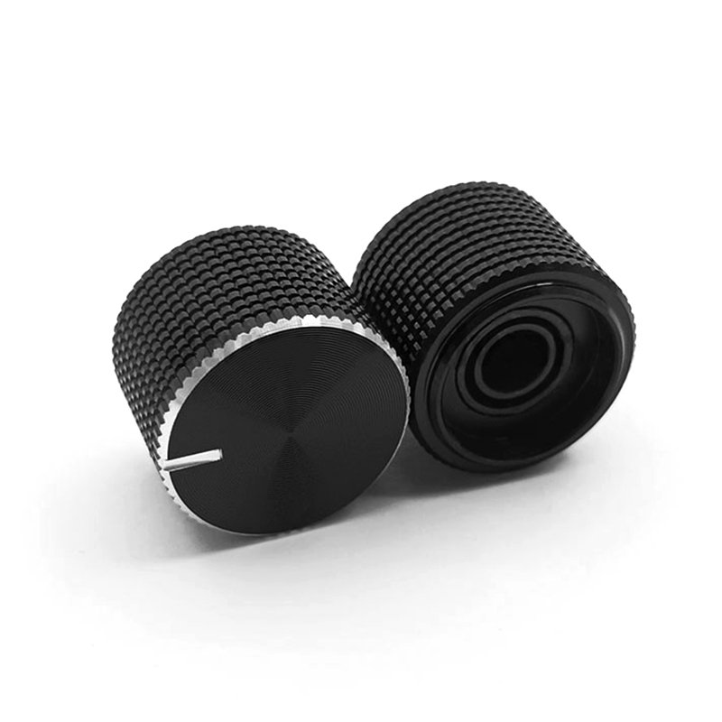
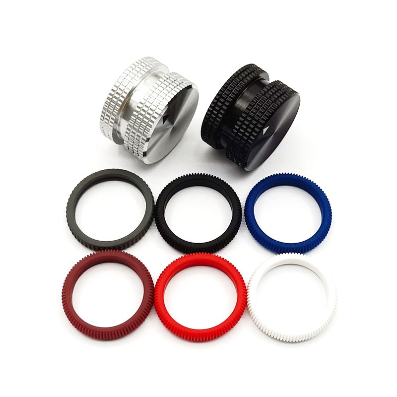
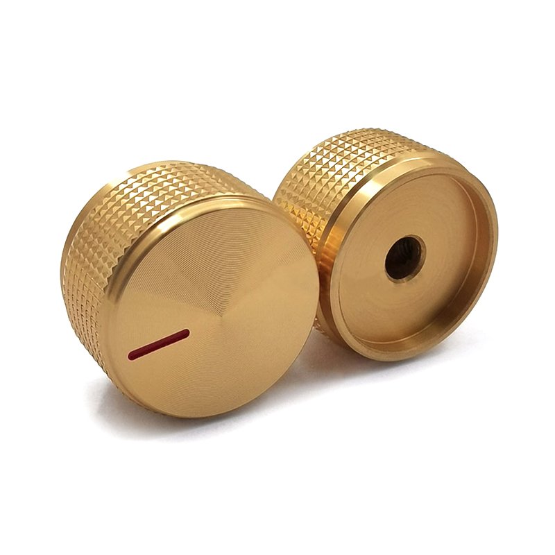
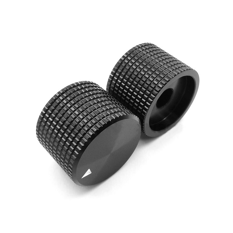
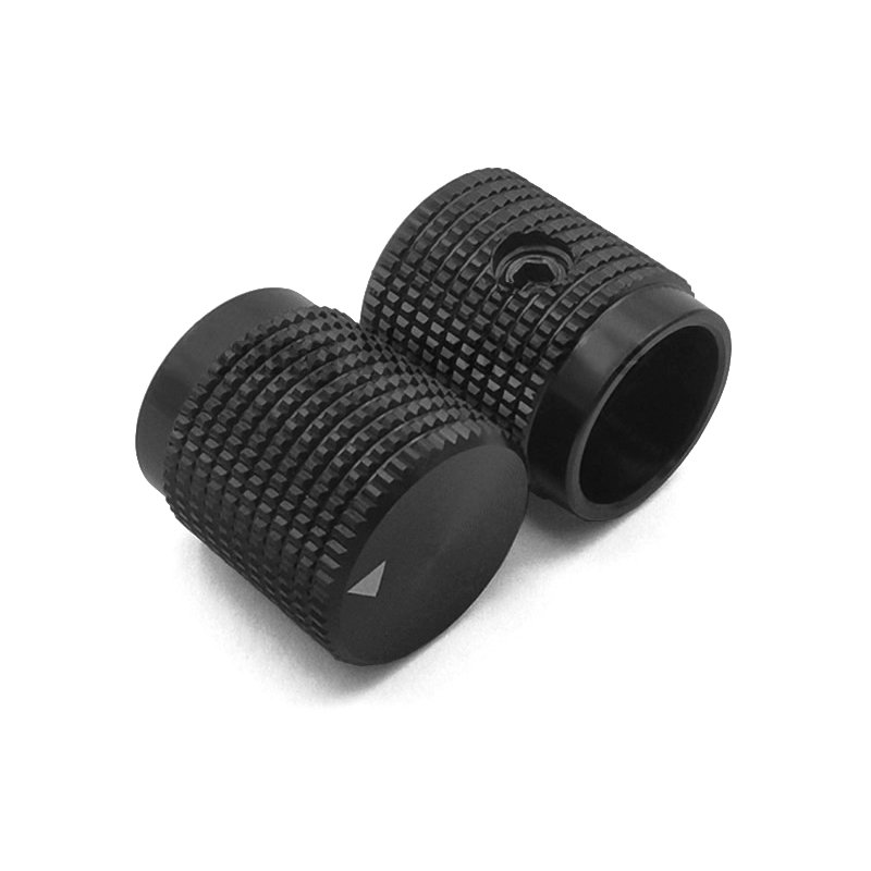
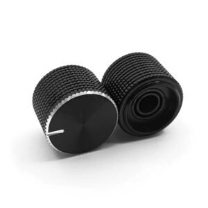
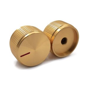
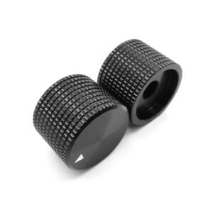
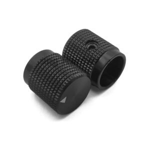
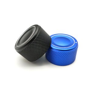
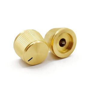
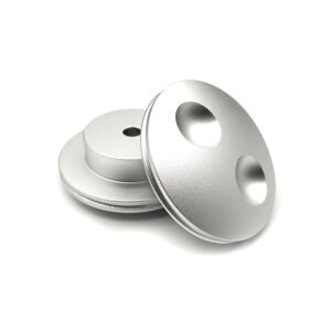
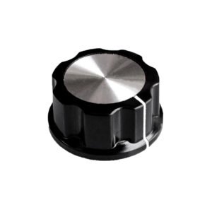
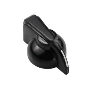
A grid knurling knob, also called a diamond-knurled knob, has a crossed texture around the grip. The body image below shows silver and black examples displayed above six colored trim rings. Specify the grip pattern, component arrangement and mounting interface for the selected design.
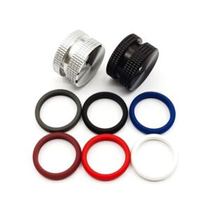
Material options include aluminum alloy, stainless steel and brass. Identify the grade, dimensions and finish on the drawing. Select the required face, indicator and trim details from the project design; confirm color and appearance references for the chosen configuration.
Grid Pattern and Mounting Details
- Grip Geometry: Define grip diameter and height, the crossed knurl pattern, pitch, angle or tool reference, pattern extent and edge condition.
- Bore and Threads: Supply the mating-component dimensions, bore size and depth, any through-hole geometry and the selected thread specification.
- Retention: Specify the selected threaded or set-screw mounting arrangement separately from the bore geometry. Include screw, thread and hole-position details where applicable.
- Panel and Markings: Show panel clearance, surrounding-component spacing and any indicator line, logo or scale artwork with its reference orientation.
Provide relevant handling and environmental requirements, including any oil exposure or vibration conditions. Agree fit, rotation and handling checks for the complete assembly, and define the pattern-consistency and edge-condition criteria for the knob.
Materials, Machining and Finish
The machining process is reviewed based on the material grade, part geometry and required quantity. Turning forms the specified profile, and diamond knurling produces the crossed texture with tooling selected for the design. Drilling, boring and tapping are used for the specified mounting features.
Specify deburring and polishing requirements for handled edges and designated surfaces. Finish options include anodizing of suitable aluminum alloys, plating, coatings, polishing and custom colors, subject to material and appearance review. Include laser-marked logos or indicators where required.
Provide prototype and production quantities and an appearance reference or sample where needed. Agree the dimensions, mounting fit, knurl pattern, finish and markings to be inspected for the selected part.
Dimensions and Inspection Requirements
Confirm the following references against the project drawing, nominal sizes, material, machining route and finish. Define controlled features, datums, measurement conditions and acceptance limits in the drawing and inspection plan.
- Outer Diameter Tolerance: ±0.02–0.05 mm
- Bore Diameter Tolerance: H7 / ±0.01–0.02 mm
- Concentricity: ≤0.02 mm
- Surface Roughness on Non-Knurled Areas: Ra ≤ 1.6 μm
- Dimensional Tolerance: ±0.02–0.05 mm
For the bore, state the nominal diameter and whether the H7 designation or explicit numerical limits govern acceptance. Define the reference axis and inspection method for concentricity. Identify the non-knurled surfaces and measurement locations governed by the roughness requirement. Define knurl pitch, geometry and pattern-consistency acceptance separately.
Control and Instrument Applications
Designs can be reviewed for industrial control panels, machinery, CNC equipment, automation systems, audio controls, electronics, laboratory and measuring instruments, and consumer hardware. Match the selected knob, interface and finish to the actual assembly and operating conditions.
Send Your Grid-Knurl Requirements
Send the part and mating-component drawings with the material grade, pattern specification, mounting method, finish and quantity. Include any indicator or trim details, critical fits, appearance samples, prototype needs and the agreed pattern and dimensional inspection criteria.
Explore our CNC machining processes or discuss your grid knurling knob requirements. You can also contact eleven@grancen.com directly.
Reviews
There are no reviews yet.