
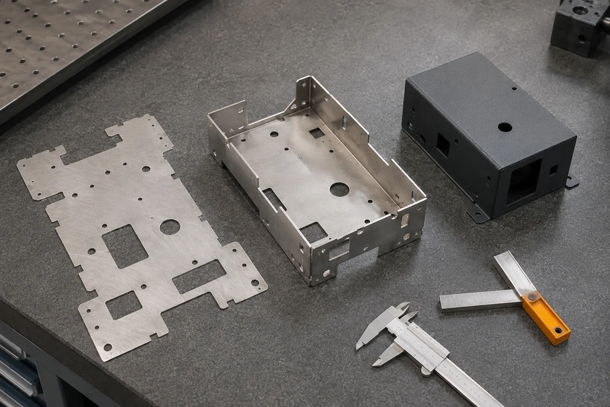
A sheet metal fabrication project succeeds when the drawing, material, forming sequence and inspection plan are considered together. Cutting a flat blank is only one step. The finished component may also depend on bend allowances, hole-to-edge relationships, hardware, joining, surface finishing and assembly access.
For an overseas engineering or sourcing team, the practical goal is to give the manufacturer enough controlled information to plan the route without forcing unnecessary assumptions. This guide explains how a sheet metal component can move from drawing review to a finished, inspected part and which decisions should be clarified before quotation.
Begin With the Part Function and Drawing
Start by defining what the component must do. Identify its mounting points, mating faces, load path, enclosure or shielding role, cosmetic surfaces and operating environment. A controlled 3D model helps communicate overall geometry, while the 2D drawing should identify critical dimensions, datums, threads, finishes and inspection requirements.
Distinguish functional requirements from preferences. A fixed interface may need close control, while a non-mating flange may allow more manufacturing flexibility. This distinction helps the supplier focus the process plan and inspection effort on the characteristics that matter to the assembly.
Select Material and Thickness as a System
Material grade and sheet thickness influence stiffness, weight, corrosion behavior, cutting conditions, bend response, joining and finish compatibility. Common project choices may include aluminum, stainless steel or carbon steel, but the right choice depends on the application and the complete production route.
Specify the required grade, temper or condition where it is functionally necessary. If alternatives are acceptable, state the properties that must be preserved and ask for review. Material substitutions should not be made from a price comparison alone because forming behavior and downstream finishing can change.
Develop the Flat Pattern Before Cutting
The manufacturing team converts the formed geometry into a flat pattern. Bend radius, material condition, tooling and the planned bend sequence affect the developed blank. For that reason, a buyer-supplied flat pattern is best treated as controlled design input that should still be checked against the intended forming method.
Laser cutting or another suitable cutting process can then create the outside profile, holes, slots and relief features. The exact route depends on material, thickness, geometry, edge requirements and quantity. Small features, narrow webs and closely spaced cutouts should be reviewed before release rather than assumed to behave identically in every sheet.
Plan Bends, Reliefs and Tool Access
Bending turns the flat blank into the working shape, but the sequence matters. One flange can block access to another, and a return bend may require different tooling or an additional setup. Clear bend direction, inside radius and angle requirements help the fabricator understand the intended geometry.
Features near a bend may distort or shift during forming. Bend reliefs, hole placement and flange length should therefore be reviewed together. When a dimension is critical after bending, define it from a functional datum on the formed part instead of relying only on a flat-state dimension.
Choose the Right Joining and Hardware Strategy
A fabricated assembly may use welding, rivets, clinch hardware, screws, tabs or another joining method. The choice affects heat input, distortion, disassembly, access, appearance and inspection. It should be made according to the assembly requirement rather than added as a late production detail.
Show hardware type, orientation and access clearly. For welded assemblies, identify the required joint locations and any surfaces that must remain controlled. Cosmetic expectations should also be stated because weld finishing and visible surfaces can require different handling from hidden structural joints.
Coordinate Deburring and Surface Finishing
Cut edges and formed features may require deburring or edge treatment before handling, assembly or finishing. Surface preparation should match the selected finish and the end-use environment. Powder coating, plating, passivation, brushing or other finishes each introduce their own design and masking considerations.
Define color or appearance requirements with an approved reference where needed, and identify threads, electrical contacts, grounding points or mating faces that must remain free of coating. If the finish adds measurable build, allow for it when reviewing fits and hardware interfaces.
Inspect the Part in Its Formed Condition
Inspection should follow the way the part functions. The plan may include material verification, flat-blank checks, formed dimensions, bend angles, hole positions, hardware installation, joint condition, surface finish and final assembly fit where applicable. Critical characteristics should be tied to the released drawing and agreed scope.
Complex sheet metal parts may not sit naturally on a flat inspection table, so the datum scheme must be practical. Discuss fixtures, measurement access and any required records before production. A clear plan reduces disagreement about whether a dimension is being checked in the intended condition.
Prepare an RFQ That Supports Process Review
A useful RFQ normally includes:
- controlled 3D and 2D files with matching revision status;
- material grade, thickness and acceptable alternatives;
- prototype, batch and expected program quantities;
- critical datums, interfaces and formed dimensions;
- joining, hardware and surface-finish requirements;
- inspection records, packaging and delivery expectations.
Label open decisions instead of hiding them. This allows the manufacturer to identify where design-for-manufacturing review can simplify the route while keeping fixed functional requirements protected.
Review the Whole Route Before Release
Sheet metal fabrication is a connected sequence, not a collection of isolated operations. A change to material, thickness, cut geometry, bend order or finish can affect downstream steps. Reviewing the route as a whole helps prevent a locally convenient decision from creating an assembly or inspection problem later.
Grancen supports sheet metal processing for custom manufacturing projects. To discuss a current component, send your drawings, material, quantity and inspection requirements for review.